
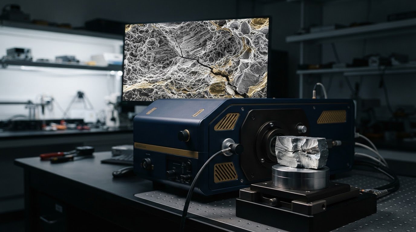
Can a fracture surface tell you why a component failed, or only show where it broke? SEM can reveal fine features that point toward fatigue, brittle fracture, or ductile failure, but a clear image isn’t a conclusion on its own. In fracture surface analysis (fractography) with SEM, the challenge is to distinguish meaningful evidence from surface damage, imaging artifacts, and features that only make sense in the context of the component’s history.
If you’re unsure where to look for a crack origin or how confidently to interpret a particular morphology, a disciplined examination helps turn visual clues into a more defensible assessment. This guide explains how SEM supports fracture-surface analysis, what common features may indicate, and where the method’s limits matter. You’ll also learn how to plan an examination, moving from an overall survey to closer imaging of the origin and propagation zones, and how to interpret observations alongside material properties, loading conditions, and service history. The goal is not to let one micrograph dictate a failure explanation, but to build an interpretation from the available evidence.
Key Takeaways
- Use fracture morphology to develop possible failure explanations, not to treat a single feature as definitive proof.
- Plan fracture surface analysis (fractography) with SEM around a clear question, careful specimen-context documentation, and progressive imaging of relevant regions.
- Compare features with the component’s material, loading history, and service conditions to distinguish meaningful evidence from misleading clues.
- Preserve the fracture surface and record component orientation and material identification to support a traceable, defensible interpretation.
- Assess SEM requirements against specimen types, feature scales, and examination frequency when planning in-house capability.
What Fracture Surface Analysis (Fractography) Can, and Cannot, Reveal
Fractography examines and interprets fracture surfaces to understand how a crack formed and advanced. Scanning electron microscopy (SEM) makes fine surface morphology visible at magnifications that can reveal details difficult to resolve through unaided inspection. These details may help investigators identify evidence relevant to a failure, but an image shows physical features, not the complete history that produced them. Fracture surface analysis (fractography) with SEM is most useful when observations are kept distinct from explanations about loading, environment, or root cause.
What information does a fracture surface preserve?
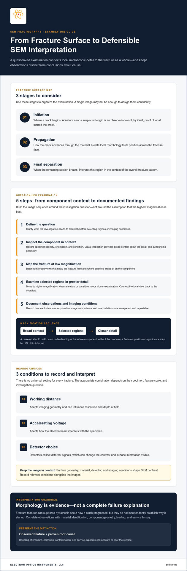
A fracture surface can preserve clues about crack growth in its overall shape and local features. Investigators commonly consider three stages: initiation, where a crack begins; propagation, as it advances through the material; and final separation, when the remaining section breaks. These are useful concepts for organizing an examination, but a single image may not provide enough evidence to assign each stage confidently.
Observed features may support a hypothesis about how fracture progressed, but they don’t independently establish what caused the crack to start. A feature near a suspected origin is an observation; linking it to a defect, a particular load, or a service condition requires corroborating evidence. Handling after failure, corrosion, contamination, and other service exposure can also obscure or alter the surface. Record the part’s condition and history before treating visible details as original fracture evidence. The field and its use in failure investigations are outlined in Fractography.
Why use SEM rather than visual inspection alone?
Visual inspection provides essential broad context: the break’s location, the component’s orientation, and the relationship between the fracture and surrounding geometry. SEM adds detailed views of microscopic morphology and a large depth of field, helping render uneven, three-dimensional surfaces more clearly across a range of magnifications. The methods serve different purposes. Close-up imaging should build on, not replace, an understanding of the whole component.
Choose magnification according to the question and feature scale. Start with context, then examine selected regions in progressively greater detail rather than assuming the highest magnification will provide the most useful evidence. A large field of view can relate features to the fracture as a whole, while a closer view may resolve local morphology. SEM image contrast is shaped by surface geometry, material, detector, and imaging conditions, so appearance can be misleading if acquisition context is ignored. For background on how the instrument forms images, consult the article on the fundamental principles of scanning electron microscopy.
Key takeaway: Fracture features inform failure analysis, but they require engineering context. A defensible interpretation connects documented observations with material identification, component geometry, loading, and service history instead of treating a striking micrograph as proof of root cause.
How SEM Imaging Makes Fracture-Surface Features Visible
A useful SEM examination follows a question-led sequence: define what the investigation needs to establish, inspect the component and fracture in context, select regions for closer study, acquire images at suitable scales, and document observations alongside imaging conditions. This keeps an attractive micrograph from becoming the whole investigation. Before imaging, record the specimen’s identity, orientation, condition, and preparation so reviewers can understand where each view came from.
Begin with low-magnification images that map the fracture face and show how selected areas relate to the component. Then move to higher magnification where a feature or transition needs closer examination. A broad view can help locate changes across the surface; a detailed view can reveal local morphology. Without the overview, however, it may be difficult to interpret a feature’s position or significance.
Magnification should follow the feature under investigation, not the assumption that the highest magnification will provide the strongest evidence. In fracture surface analysis (fractography) with SEM, a disciplined sequence connects local detail to the larger fracture pattern.
Choosing imaging conditions for the fracture feature
Imaging conditions influence which information is emphasized. Working distance affects imaging geometry and can influence resolution and depth of field, while accelerating voltage affects how the electron beam interacts with the specimen. Detector choice matters too: detectors collect different signals, so changing detectors can change the contrast and surface information visible in an image.
There is no universal setting for every fracture. The appropriate combination depends on the specimen, feature scale, and investigation question. A setting that makes surface relief easier to interpret may not suit another analytical objective. Record working distance, accelerating voltage, detector, and other relevant conditions alongside the images to make comparisons more transparent and repeatable. Understanding broader imaging principles can help explain how these variables shape SEM observations.
Preparing and handling a fractured specimen
Preserve context before preparation. Photograph and document the component, fracture location, orientation, and condition, then handle the specimen in a way that minimizes contact with the fracture face. Avoid touching or cleaning areas that may hold evidence of crack growth, contamination, or environmental exposure. Even minor disturbance can complicate interpretation.
Select conductive coating and vacuum conditions for the specimen and analytical objective rather than applying them automatically. Preparation can affect what is visible or measurable, and a coating may influence subsequent elemental analysis. Document any coating, cleaning, or other treatment so observations can be interpreted with those factors in view.
For laboratories planning in-house examinations, let imaging needs guide instrument evaluation. Consider specimen range, feature scales, desired analytical information, and expected examination frequency together. Reviewing SEM system options can be one part of capability planning, alongside training and ongoing equipment support.
How to Interpret SEM Fractography: Distinguishing Common Failure Features
SEM images can reveal fracture morphologies associated with different failure mechanisms, but interpretation takes more than matching a feature to a label. Treat each morphology as evidence to compare with the material, fracture location, and component history. Terminology also has limits: descriptions such as transgranular and intergranular refer to a crack’s path through the microstructure, while features such as dimples describe surface morphology. Neither category alone establishes why failure occurred.
| Observed morphology | Possible mechanism | Interpretation caution |
|---|---|---|
| Dimples or microvoid coalescence | Often associated with ductile fracture, as voids form and join during deformation | Dimple appearance and distribution vary with material and local stress state; confirm the broader fracture pattern. |
| Faceted regions consistent with cleavage | May indicate brittle, transgranular fracture through grains | Facet-like appearance is not sufficient by itself to identify cleavage or explain the conditions that produced it. |
| Crack path following grain boundaries | May indicate intergranular fracture | Relate the path to the material’s microstructure and service history; a boundary-following appearance does not identify the cause. |
| Striations or other progression markings | May support a fatigue-crack interpretation | Markings can be faint, absent, obscured, or confused with other surface patterns; assess their position and continuity. |
| Secondary cracks | Can accompany crack propagation or local fracture processes | Their presence alone does not determine the primary mechanism or locate the original crack origin. |
Ductile fracture, brittle cleavage, and grain-boundary separation
Microvoid coalescence is commonly associated with ductile fracture: microscopic voids grow and link, leaving a dimpled surface. By contrast, transgranular cleavage describes fracture through grains and may produce relatively flat facets. Intergranular fracture follows grain boundaries. These terms describe different aspects of the fracture path and surface; they aren’t interchangeable labels for a complete root-cause finding.
Material structure and loading history influence which features form and how they appear. Interpret morphology in light of the material, its microstructure, and the conditions the component experienced. Similar-looking features may arise in different contexts, and more than one fracture process may contribute to a single surface.
Fatigue features, crack origins, and secondary cracking
Striations and other progression markings can support a fatigue assessment when their form, location, and pattern fit the surrounding evidence. To identify a probable origin, look for converging clues across the fracture surface, including changes in propagation direction and the relationship between the suspected initiation region and the component’s geometry. No single marking should carry that conclusion alone.
Surface damage, corrosion, contamination, or handling can obscure diagnostic patterns. Some materials and fracture conditions may also leave features that are difficult to resolve. Morphology supports mechanism assessment, not standalone causal proof. In fracture surface analysis (fractography) with SEM, a defensible interpretation combines multiple observations with material and engineering context rather than relying on one compelling image.
A Defensible Fractography Workflow: From Failed Part to Findings
A reliable fractographic investigation depends on preserving evidence and keeping a traceable connection between each observation and the part it came from. SEM images are one element of that record, not a substitute for component history or engineering analysis. A structured workflow helps distinguish what was directly observed from what those observations may indicate, while making uncertainties visible rather than concealing them.
Preserving evidence and building the examination record
Before repositioning, separating, cleaning, or preparing the failed part, photograph the full component and fracture as received. Capture orientation, fracture location, and the relationship between the break and nearby features. Assign sample identifiers and record who handled the part, how it was stored, and any preparation performed. Preserve relevant manufacturing information and note suspected loading, service conditions, and timing of failure.
Build the examination from representative areas, retaining overview views alongside detailed SEM images. Each close-up should remain traceable to its location on the component; otherwise, it may be difficult to relate a feature to crack progression or geometry. Record imaging conditions and specimen treatment with each image set. Careful SEM sample preparation should preserve relevant surface evidence and be documented so its possible influence on observations is clear.
Combining SEM observations with other evidence
Interpretation gains strength when independent information can test a proposed mechanism. Compare SEM observations with the broader fracture appearance, material identification and records, component design, and known loading and service history. For example, a suspected fatigue feature may be consistent with repeated loading, but the load history and the feature’s location must also make engineering sense. If evidence conflicts, document the discrepancy and keep alternative explanations open.
EDS can add elemental-composition information from selected regions. It may help assess whether a deposit or local compositional difference is present, but composition alone does not establish when or how that material arrived, nor does it prove the cause of fracture. Interpret EDS results alongside SEM morphology, specimen history, and other relevant evidence. Keep measured results distinct from conclusions drawn from them.
In the final report, separate four elements: observations (what the examination directly shows), plausible mechanisms (interpretations consistent with those observations), alternative explanations (other reasonable interpretations), and unresolved questions (information the available evidence cannot settle). This structure makes the reasoning auditable and prevents a tentative mechanism from being presented as a confirmed root cause. A defensible conclusion states both the evidence supporting it and its limitations.
For laboratories planning in-house imaging, match SEM capability, operator training, and ongoing equipment support to the specimens and analytical questions involved. Explore SEM systems and support for capability planning related to fracture-surface examination.
Planning SEM Capability for Fracture Surface Analysis
Planning in-house fracture surface analysis (fractography) with SEM starts with the specimens and decisions the laboratory needs to support, not with a preferred instrument category. A program examining small, regularly sized coupons has different practical requirements from one handling large or irregular components. Likewise, locating an overall fracture region, resolving fine surface morphology, and collecting compositional information are distinct objectives that may call for different instrument configurations.
Translate the investigation’s needs into a short capability profile before evaluating systems:
- Specimens: Identify typical dimensions, shapes, materials, and preparation constraints.
- Feature scales: Define the surface details the examination must resolve, from broad fracture patterns to localized morphology.
- Analytical objectives: Distinguish imaging needs from questions that may also require elemental analysis, such as examining a deposit.
- Workflow: Estimate how often samples will be examined, who will operate the instrument, and how results will be documented.
This profile makes trade-offs explicit and helps the laboratory assess whether a planned configuration aligns with its actual work.
Matching laboratory requirements to an SEM system
Compare specimen dimensions and material types with the system’s sample-handling requirements, then consider desired feature detail, imaging conditions, and expected examination frequency. If compositional evidence is part of the workflow, account for EDS as a separate analytical requirement rather than assuming imaging alone will answer every question. Application fit depends on the specimen, evidence sought, and instrument configuration; no single SEM setup is automatically appropriate for every fractography task.
Electron Optics Instruments, LLC offers the Cube II Benchtop SEM for laboratories assessing their in-house microscopy needs. Evaluate it against the same defined requirements used for any system under consideration, without assuming performance based on the product category alone. A well-structured capability review focuses on whether the configuration and workflow address the laboratory’s specimens and analytical objectives.
Building confidence through training and equipment support
Instrument capability is only part of a dependable examination process. Training can help operators use consistent imaging and documentation practices, preserve traceability between images and specimen regions, and recognize when observations need further investigation. Ongoing maintenance and repair support also matter to laboratories planning regular SEM use, since equipment care is part of sustaining an effective workflow over time.
Electron Optics Instruments, LLC draws on more than 30 years of industry experience and offers SEM maintenance, repair, and on-site training. These services can support laboratories as they develop in-house SEM workflows and build operator confidence. Product selection and training should remain connected: the instrument must suit the work, and users need the knowledge to operate it consistently.
For a practical next step, define your sample types, feature scales, analysis goals, and expected usage, then explore SEM systems and laboratory support in relation to those requirements.
Build Your Next Step Around Laboratory Needs
Turn the questions raised by a fracture investigation into a practical plan for future examinations. Identify which sample types your laboratory expects to handle, what evidence its investigations need, and how consistently images and observations must be documented. This planning can clarify whether in-house SEM access would support your workflow and which capabilities should guide system selection.
Keep the purpose specific. Fracture surface analysis (fractography) with SEM can contribute valuable evidence, but equipment decisions should support a broader process in which observations are interpreted alongside engineering context. Consider how users will build confidence with the instrument and maintain consistent examination practices as laboratory needs develop.
Electron Optics Instruments offers SEM systems, including the Cube II Benchtop SEM, alongside maintenance, repair, and on-site training. Explore SEM systems and laboratory support to align instrumentation and ongoing support with your work.
Frequently Asked Questions
Can SEM fractography determine the exact root cause of a component failure?
No. SEM fractography reveals physical evidence that can support an assessment of the failure mechanism, but it can’t establish the exact root cause on its own. In fracture surface analysis (fractography) with SEM, observed morphology must be considered alongside material properties, design, loading, manufacturing records, and service conditions. For example, a feature consistent with fatigue still needs to be evaluated against the part’s load history. Alternative explanations may also need testing before reaching a conclusion.
Does SEM fractography work for polymer materials?
Yes, polymer fracture surfaces can be examined with SEM, but imaging and preparation should be selected for the polymer and the question being investigated. Ductile behavior may leave evidence of deformation, while brittle behavior may produce a different surface pattern; neither appearance is universally diagnostic. A polymer’s structure, processing history, additives, and loading conditions can all affect fracture morphology. Interpret images in that material-specific context rather than applying assumptions from metals.
Can a fracture surface be cleaned before SEM examination?
Sometimes, but cleaning can remove unwanted contamination and also dislodge or alter evidence that may matter to the investigation. The appropriate decision depends on how the specimen was handled, what exposure it experienced, and whether deposits or surface residues are relevant to the analysis. Document the part and its condition before intervening, and preserve an unaltered region when feasible for comparison. There’s no universally appropriate cleaning method or solvent for every fracture surface.
Is conductive coating always required for SEM fractography?
No. Whether coating is appropriate depends on the specimen’s conductivity, charging behavior, instrument conditions, and the information sought. A coating may help manage charging in some examinations, but it can also affect later surface analysis or elemental characterization. Before preparation, consider whether EDS or another follow-on examination is planned and whether an uncoated region should be retained. Choose preparation according to the sample and analytical sequence, not as an automatic step.
Can EDS identify the cause of a fracture?
No. EDS reports elemental-composition information from selected regions; it doesn’t directly determine the mechanical failure mechanism or prove root cause. It may help investigate a deposit near a crack origin, an inclusion, or a suspected material difference. Those results still require context: a detected element alone may not show when or how it became present. Compare EDS findings with surface morphology, specimen history, and other relevant engineering evidence.
How much magnification is needed for SEM fracture surface analysis?
There’s no single magnification that suits every fracture examination. Start with views that show where a region sits on the fracture, then increase magnification to inspect a feature relevant to the investigation, such as a small marking or local transition. Record image scale and acquisition conditions so views can be compared and traced to their locations. The useful field of view and resolved detail depend on the instrument configuration and imaging conditions.