
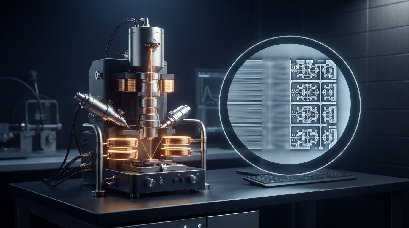
A sharp SEM image requires more than bringing the beam into focus: astigmatism can blur details in different directions. This guide explains astigmatism correction in SEM. A stigmator adjusts the beam using two pairs of coils, one for X-axis correction and one for Y-axis correction. These adjustments compensate for beam asymmetry and help restore a more circular cross-section at the focal point.
If an image sharpens in one direction but remains smeared in another, the cause may be in the electron optics rather than the specimen. Astigmatism creates two focal positions, so blur appears along perpendicular directions on either side of focus. Between them, the beam forms a minimum circle of confusion. Here, you’ll learn what astigmatic difference means, how lens asymmetry can produce blur, and how stigmator adjustments help bring the image into focus. Understanding these relationships makes it easier to assess image quality and distinguish astigmatism from other focus problems.
Key Takeaways
- Compare image blur on either side of focus: directional changes can help distinguish astigmatism from a simple focus error.
- Use the astigmatic difference to describe the separation between the two focal positions and understand the extent of the blur.
- Consider lens-field irregularities and mechanical misalignment as possible sources of beam distortion.
- Use stigmator adjustments to compensate for beam asymmetry; Electron Optics Instruments’ Cube II Benchtop SEM is one SEM option to explore for imaging work.
Astigmatism-related image blur in SEM
Astigmatism blur occurs when an SEM beam focuses differently across two perpendicular directions. Its effect is visible at the 5 kV imaging condition described here.
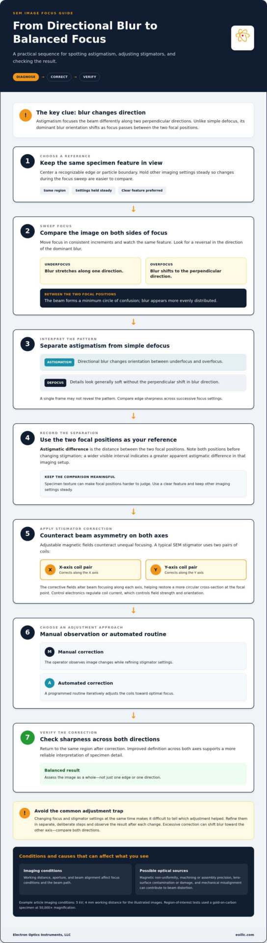
At underfocus and overfocus, blur stretches along perpendicular directions; at exact focus, it becomes more evenly distributed. The two focal positions leave a minimum circle of confusion between them. This directional pattern helps diagnose astigmatism and differs from the uniform softness caused by simple defocus. Astigmatism can reduce resolution and obscure specimen details needed for accurate analysis.
Working distance, aperture, and beam alignment affect the focus conditions and beam path, so they can influence how astigmatism appears. For example, the illustrated images used a 4 mm working distance; aperture selection affects beam formation, while misalignment can complicate interpretation of directional blur.
Manual and Automated Correction
Manual and automated correction are two ways to adjust SEM stigmators and reduce directional blur. With manual correction, the operator refines the image while changing stigmator settings. Automated routines iteratively adjust the coils toward optimal focus. Both methods address beam asymmetry through X- and Y-axis correction. Manual adjustment depends on observing image changes, while automation follows its programmed routine.
Stigmation Adjustment Mistakes and Risks
Stigmation mistakes can make focus harder to diagnose or worsen image sharpness. A common error is changing focus and stigmator settings at the same time, making it difficult to tell which adjustment helped. Instead, refine focus and stigmation in separate, deliberate steps, observing the result after each change. Excessive correction can shift blur toward the other axis, so compare sharpness in both directions rather than optimizing one edge alone.
SEM image quality depends on resolving specimen detail without mistaking blur for a surface feature. In the described region-of-interest tests, a gold-on-carbon specimen was imaged at 50,000× magnification. Directional softness can conceal fine boundaries or create misleading edge shapes. Check the same region after correction; improved definition across both axes supports a more reliable interpretation.
Astigmatic difference
Astigmatic difference is the distance between the two focal positions caused by astigmatism. To distinguish astigmatism from defocus, sweep focus and observe whether the direction of the blur changes.
Astigmatism Versus Defocus
Astigmatism versus defocus comes down to directional blur versus general softness. During an SEM focus sweep, astigmatic blur changes orientation between underfocus and overfocus. Ordinary defocus softens details without that perpendicular shift. Compare the same specimen feature at successive focus settings. A reversal in the dominant blur direction points more strongly to astigmatism than uniform softness. This distinction helps separate the need for optical correction from a simple focus offset.
Image Clues for Astigmatism
Image clues for astigmatism include changes in edge sharpness as focus moves. At one focal position, edges may appear stretched along one axis. As focus passes through the other position, the dominant blur shifts to the perpendicular axis. Near the central setting, blur becomes more evenly distributed. This sequence tells you more than judging a single frame.
To assess an SEM image, choose a recognizable edge or particle boundary and keep the same region centered during the focus sweep. Move focus in consistent increments, then compare edge sharpness in different directions. If a horizontal feature sharpens while a vertical feature remains smeared, continue through focus and look for the reverse pattern. This comparison helps distinguish directional astigmatism from a simple focus offset.
Focal separation describes an optical condition, not a specimen dimension. A wider visible interval between the directional focal positions indicates a greater apparent astigmatic difference in that imaging setup. Specimen texture can make the positions harder to judge. Repeat the sweep using a clear feature while holding other imaging settings steady. Note both positions before adjusting stigmation. This gives the operator a practical reference for the correction step.
Astigmatism in electron lenses
Electron-lens astigmatism occurs when beams along perpendicular axes focus at different positions. SEM stigmators correct it by applying adjustable magnetic fields that compensate for beam asymmetry.
SEM Astigmatism Correction
SEM astigmatism correction compensates for unequal focusing in electromagnetic lenses. Axial asymmetry can result from magnetic non-uniformity or limited precision during machining and assembly. These differences affect how the lens focuses electrons across the beam. Contamination or damage on lens surfaces can also create uneven fields and distort the beam.
Mechanical misalignment in the lens system or other SEM components can also introduce astigmatism. Operators can distinguish possible causes by observing their effect on the image, then correct beam asymmetry with stigmator settings. The lens produces the underlying distortion; the stigmator applies a counteracting field. This separates the optical cause from the correction mechanism.
Stigmator Correction
Stigmator correction uses adjustable magnetic fields to counteract beam asymmetry. SEM stigmators typically use two pairs of coils, one pair for X-axis correction and another for Y-axis correction. The fields alter the beam’s focusing along each axis, helping restore a more circular cross-section at the focal point.
SEM control electronics regulate the current supplied to the coils, controlling the strength and orientation of each corrective field. An operator can adjust settings manually while observing focus, or use an automated routine that adjusts the coils iteratively. Some advanced SEMs use feedback systems to monitor beam shape and adjust stigmators as imaging conditions change.
For a practical correction, first establish focus on a clear specimen feature. Then adjust stigmator settings to reduce directional blur, making controlled changes across both axes. Reassess the same feature after each adjustment. If one direction sharpens while another remains distorted, refine the corresponding correction rather than shifting focus alone. Lens asymmetry explains why this axis-by-axis approach matters: the beam’s two focal positions need not coincide. The goal is a more balanced beam at focus, not simply a sharper-looking edge in one direction.
How is astigmatism corrected in scanning electron microscopy?
Astigmatism correction uses a stigmator to counteract uneven focusing in an SEM. Its adjustable magnetic fields compensate for beam asymmetry and help restore a more circular beam cross-section at focus. Astigmatism correction in SEM, explained as a practical workflow, starts with observing how the image responds to adjustment.
SEM stigmators typically use two pairs of coils: one pair corrects the X axis, and the other corrects the Y axis. SEM control electronics regulate the current supplied to the coils, changing the strength and orientation of each corrective magnetic field. This axis-specific adjustment targets unequal focusing rather than simply shifting the image’s focus setting.
A practical correction sequence connects visible image changes with coil adjustments:
- Bring a recognizable specimen feature into focus before changing stigmator settings.
- Adjust the X- and Y-axis corrections while observing the same feature.
- Refine the settings until focus appears more balanced across both directions.
Manual correction lets an operator change stigmator settings and judge the image response directly. Automated routines can instead adjust the coils iteratively toward optimal focus. Some advanced SEMs use feedback systems to monitor beam shape and adjust stigmators as imaging conditions change. Both approaches use the coils to compensate for beam asymmetry.
Interpret the response carefully. If a feature sharpens along one axis but remains blurred along the other, the correction may need further refinement. Reassess the same region after each adjustment. Changing focus and stigmator settings together makes it harder to identify which change improved the image. Astigmatism correction in SEM, explained through this controlled comparison, ties each adjustment to visible results.
These adjustments address optical beam asymmetry; they don’t remove every source of poor image quality. For SEM systems used in imaging applications, explore SEM system options as a next step toward matching equipment to your work.
Electron Optics Instruments: Cube II Benchtop SEM
Electron Optics Instruments offers the Cube II Benchtop SEM as an option for teams evaluating SEM equipment for industrial or research imaging. Understanding astigmatism can help clarify what to assess in image quality and focus when considering a system for your work.
The Cube II Benchtop SEM is one option alongside the Genesis Tabletop SEM and Veritas Series SEM. Compare these systems with your imaging requirements and intended applications. Because astigmatism correction depends on the interaction between the beam, lens system, and stigmator adjustments, selecting equipment suited to your needs is part of building an effective imaging workflow.
Contact Electron Optics Instruments to discuss SEM options for your imaging needs.
Build a More Reliable SEM Imaging Workflow
A repeatable imaging log helps teams compare results across specimens and sessions. Record the conditions and adjustments associated with a clearly resolved image, then use that baseline when reviewing later scans. Astigmatism correction in SEM, explained as part of a documented workflow, can make image evaluation more consistent. It also gives operators a shared reference for assessing whether a change reflects the imaging setup or the specimen.
For your next step, match SEM equipment to your sample requirements, desired image detail, and daily workflow. Astigmatism correction in SEM, explained in this practical context, connects optical adjustments with the broader decisions that support dependable imaging. Electron Optics Instruments can help you consider SEM options for your application.
Contact Electron Optics Instruments to discuss your SEM imaging requirements. A considered workflow is a strong foundation for clearer, more useful observations.
Frequently Asked Questions
How do I get a good image?
Start with a representative specimen feature and keep imaging conditions consistent while refining the image. Check that the feature has clear edges, then assess whether its details are equally defined in different directions. If only one orientation remains soft, investigate beam correction before interpreting the blur as specimen structure. Save or record the settings once the feature is clearly resolved, so later images can be compared with the same baseline.
What are the steps to adjust SEM focus and stigmation?
Use a controlled sequence so each change has an interpretable effect:
- Select a specimen detail with visible edges and bring it into focus.
- Adjust stigmation while keeping the same detail in view.
- Refine focus again, then reassess sharpness across both directions.
Avoid changing several image controls at once. If clarity shifts, you’ll know which adjustment caused it and can retain the settings that improve the image.
What causes astigmatism in an SEM?
Uneven electron-lens focusing can produce astigmatism even when the specimen stays unchanged. Lens-surface contamination or damage, axial asymmetry, and mechanical misalignment can each affect beam symmetry. To narrow down the cause, compare the focus pattern on another clear specimen feature under the same setup. If the directional effect persists, the lens system or alignment is more likely relevant than specimen texture alone.
What SEM image settings help when correcting astigmatism?
Keep accelerating voltage, working distance, aperture, probe current, and beam alignment steady while adjusting stigmation. Changing these conditions during correction can make image changes difficult to interpret. Choose settings suited to the imaging task, then refine beam correction on a clearly defined specimen feature. Once focus is balanced, record the setup so subsequent images from the same workflow remain comparable.
What does SEM mean in astigmatism correction?
SEM means scanning electron microscopy.