
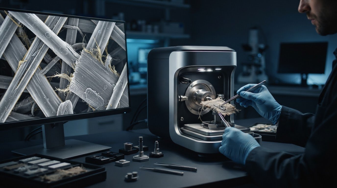
Magnification alone won’t make a textile SEM image reliable. When analyzing fiber and textile microstructures, important decisions often happen before imaging: which regions to sample, how to preserve delicate features, and how to distinguish real morphology from coating, charging, or handling artifacts. SEM can reveal fine detail in fiber shape, yarn construction, surface damage, and suspected defects, but those observations are useful only when the method produces a representative, interpretable view.
This guide explains how to plan an SEM examination around your research question, choose an imaging and analysis approach, and prepare fibers and fabrics without unnecessarily obscuring their structure. It also covers acquisition choices and clues for separating specimen features from preparation or imaging effects. The goal is to produce observations that can be documented, interpreted, and used to guide further testing, not simply a high-magnification image.
Key Takeaways
- Match the SEM examination to the question, whether you’re assessing fiber surfaces, cross-sections, interfaces, or textile construction.
- Use a deliberate sampling and preparation workflow, adapting mounting and preparation to the specimen and features of interest.
- Choose between SEM imaging, optical microscopy, and EDS according to what each method can answer and its limitations.
- Start with a survey image, then record sample location, preparation, instrument settings, and scale to support repeatable interpretation.
- When evaluating SEM equipment for textile analysis, consider sample requirements, analytical needs, throughput, and operator experience, not magnification alone.
What Can Analyzing Fiber and Textile Microstructures Reveal?
Scanning electron microscopy (SEM) produces detailed images of selected regions, making it useful for examining fiber surfaces, cross-sections, interfaces, and textile construction at fine scale. Its value depends on the question and on where and how the sample is prepared. A single exposed fiber, for example, cannot represent an entire yarn or fabric. Understanding the operating principles and signals of a Scanning Electron Microscope (SEM) helps clarify what its images can and can’t establish.
SEM microstructure analysis examines selected fiber and textile features at fine scale to describe their visible form and arrangement, not to establish every material property. It may help investigate surface damage, fracture patterns, visible treatments, or how fibers contact and pack together.
Which fiber and textile features can SEM show?
Viewed lengthwise, a fiber may show surface texture, cracks, abrasion, breaks, or a visible coating. A cross-section can show fiber shape and, when preparation preserves the structure, layers, voids, or interfaces. These views address different questions: a surface image may help locate wear, while a cross-section may be more useful for assessing internal geometry or a coating boundary.
Let textile geometry guide sampling. A single fiber shows individual morphology; a yarn also reflects twist, fiber packing, and contact between fibers; a fabric adds construction such as weave or knit, as well as differences between its faces and directions. Select locations relevant to the question, such as a damaged region and an apparently intact comparison area, and record where they are. One image of a convenient surface may miss variation across yarns, fabric directions, or the textile’s thickness.
What SEM images cannot establish by themselves
An SEM image documents visible morphology under particular preparation and imaging conditions. It does not, by itself, identify a polymer or prove the chemical composition of a surface treatment. Elemental analysis, such as EDS when appropriate to the question and instrument configuration, can add compositional information, but it does not replace every form of material identification. Claims about strength, durability, or other bulk behavior require complementary tests designed to measure those properties.
Images also represent selected fields, not the whole textile. Preparation can alter delicate fibers or obscure features, and imaging conditions can affect contrast and apparent detail. Interpret observations in light of sample location, preparation, and the question being tested. Use additional fields or complementary methods when a broader conclusion is needed.
How to Prepare Fiber and Textile Samples for SEM
Preparation should preserve the feature under investigation, not simply make a specimen fit on a stub. Geometry matters: a loose fiber, twisted yarn, woven fabric, and cut cross-section each present different surfaces and interfaces. Use a consistent workflow, then adapt mounting and preparation to the specimen and imaging method.
Choosing representative fiber, yarn, and fabric regions
Select locations according to the research question. To investigate a snag, for example, include the affected area and a suitable comparison region. Record each location relative to the fabric face, yarn direction, and surrounding construction. If the textile may vary across its area, examine multiple fields or specimens rather than treating one image as representative.
Before cutting or mounting, document the sample’s condition and available treatment history. Note fiber orientation, which fabric face is being examined, and any handling or cutting that could alter the surface. This overview of SEM sample preparation places these decisions within the broader operating workflow.
Mounting, coating, and avoiding preparation artifacts
Secure the specimen and orient it to expose the target region. Electrical contact between the specimen and mount may also matter, depending on the material and method. Single fibers may be positioned to expose a longitudinal surface; yarns need support that avoids disturbing twist or fiber packing. Mount fabric surfaces without introducing folds or compression. For cross-sections, choose a cutting and support method that preserves the boundary being examined.
Preparation can change what an image appears to show. A conductive coating may reduce charging in some workflows, but it can also alter apparent surface texture or obscure fine features. Check that the preparation suits the target feature and any planned complementary analysis. A smoother-looking or higher-contrast image is not necessarily more representative.
- Charging: Unstable contrast or image distortion can complicate interpretation of nonconductive fibers.
- Contamination: Residue from handling or preparation may resemble deposits or surface treatments.
- Compression and cutting damage: Flattened fibers, torn edges, or displaced layers may be preparation effects rather than original structure.
Inspect the mounted specimen for movement, debris, and obvious damage before collecting detailed images. If you’re developing a method, discuss the sample type, target features, and workflow requirements with SEM application and training specialists before settling on a preparation protocol.
How to Choose SEM Imaging and Complementary Analysis
Start with the evidence you need, not the highest available magnification. A surface defect, a fiber’s overall shape, and the elemental composition of a deposit are different questions and may call for different methods. Magnification alone cannot show whether an image is informative: sampling, contrast, imaging conditions, and the feature’s scale all affect interpretation.
| Method | Useful for questions such as | Key limitation |
|---|---|---|
| SEM imaging | What does a fiber surface, fracture, coating, or interface look like at fine scale? | Shows morphology and contrast, not definitive chemical identity or bulk properties. |
| Optical microscopy | Where are features located across a fabric, and how are fibers or yarns oriented? | Fine surface detail may not be resolved at the scale needed for a specific question. |
| EDS | Which elements are present in a selected region? | Elemental information alone doesn’t identify a polymer or fully characterize a treatment. |
When SEM is more useful than optical microscopy
Optical microscopy can efficiently survey fabric construction, locate a defect, or help select regions for closer study. SEM is useful when the question concerns finer surface morphology, such as small fracture features or coating texture. Neither method is universally superior. Use the method whose scale and contrast address the feature, and combine them when you need both a broad overview and a detailed examination.
How imaging conditions shape the observation
Accelerating conditions influence the signals generated and the region contributing to image contrast. Detector choice affects which signal is collected and how surface shape or material contrast is represented. Working distance also influences imaging characteristics, including resolution and depth of field. Nonconductive fibers may charge, creating brightness shifts, streaks, or distortion that can be mistaken for structure. Adjust these variables for the specimen and objective. Exact settings depend on the instrument and sample, so verify them rather than treating one setup as universal.
When EDS adds information to fiber imaging
SEM imaging describes visible morphology; EDS provides elemental information from a selected region. EDS can help assess whether an observed deposit contains elements of interest, but it does not, by itself, provide complete polymer identification. Interpretation depends on sample composition, coating, geometry, and instrument configuration. For broader context on analytical methods, consult this guide to advanced SEM techniques.
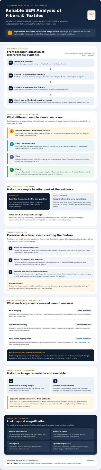
How to Capture and Interpret Repeatable Fiber Microstructure Images
Repeatable SEM images depend on a controlled sequence, not on collecting the largest possible number of close-ups. Each detailed view should be traceable to its sample location and the conditions under which it was captured. That context makes comparisons more meaningful and helps distinguish material differences from changes in imaging setup.
A practical image-capture sequence
- Survey the mounted sample at low magnification. Identify the textile region and its orientation. Check for unexpected damage or contamination before choosing areas for detailed imaging.
- Capture contextual views. Record an overview that locates the target within a fiber, yarn, or fabric, followed by detail images of the feature relevant to the research question.
- Check image quality and scale. Confirm focus, contrast, charging behavior, and scale-bar calibration before capturing images intended for comparison.
- Log the observation. Record sample identity, field location, fiber or fabric orientation, preparation details, instrument settings, detector, magnification or scale, and a relevant date or run identifier.
For comparisons, keep conditions as consistent as practical. Align fiber orientation, choose equivalent locations, and use comparable preparation and imaging settings. If a setting must change to obtain a usable image, document the change rather than treating the resulting views as directly equivalent.
Interpreting morphology without overclaiming
Describe what the image shows before assigning a cause. For example, report “longitudinal grooves and localized surface pits” before proposing abrasion, processing, or treatment as an explanation. A visible feature may be consistent with a suspected mechanism, but an image alone may not establish when or how it formed. State whether charging, coating, cutting, or other preparation effects could influence the observation.
Review multiple fields and, where possible, more than one specimen to assess whether a feature recurs. Representative sampling supports reliable comparison by showing whether a feature recurs across relevant locations rather than appearing in a single selected field. Report the scope of sampling and any limitations so readers can distinguish observed evidence from interpretation.
Consistent records make it easier for colleagues to review images and reproduce comparisons. If you’re developing an SEM imaging workflow, review SEM workflow and training options with Electron Optics Instruments.
How to Evaluate SEM Equipment and Support for Textile Analysis
Choose an SEM by how well it fits your laboratory’s samples and questions, not by configuration labels alone. Consider whether the instrument can accommodate prepared specimens, image the features of interest, support any required elemental analysis, and fit expected sample throughput and operator experience. A benchtop system may suit some workflows, while another configuration may better align with different sample or analytical requirements. Compare capabilities with defined needs rather than assuming one format is universally superior.
Questions to ask when evaluating an SEM for fibers
Describe representative specimens and the planned workflow before selecting a system. Ask the vendor to confirm compatibility with sample dimensions and preparation methods, and identify the detectors, imaging modes, and analytical options available for the specific model. If EDS is required, verify that it can be integrated with the proposed instrument and workflow. Also assess interface usability, expected throughput for your team’s work, and available operator training.
Include service and maintenance in the evaluation. Clarify what support is offered, how preventative maintenance is handled, and whether training can address the laboratory’s intended applications. These factors affect how effectively a system can be incorporated into routine work.
Applying the workflow to a benchtop SEM evaluation
The Cube II Benchtop SEM is one instrument a laboratory may evaluate against its textile requirements. Don’t assume compatibility based on the benchtop designation. Confirm sample dimensions, preparation needs, imaging modes, detector configuration, and any EDS requirements for the specific system. A useful evaluation starts with representative specimens and target observations, then checks whether the full workflow, from mounting through data capture, is appropriate.
Electron Optics Instruments distributes SEM systems in the United States and supports customers with installation, service, preventative maintenance, repairs, and technical training. When assessing a system, discuss application requirements and the support needed to develop the method. The SEM operating guidance provides broader context for planning instrument use.
Prepare a short list of sample types, target features, throughput needs, and analytical goals before discussing options. Review Electron Optics Instruments’ SEM options and support to assess how an instrument may fit your workflow.
Build a More Reliable Textile SEM Workflow
Reliable SEM analysis begins with a clear question and representative sampling. It then depends on preparation and imaging choices that preserve the features under study. Compare like with like, document settings and sample locations, and separate visible morphology from interpretation. This produces observations that are easier to assess and repeat. Complementary methods may be needed when the question extends beyond what an SEM image can establish.
For teams analyzing fiber and textile microstructures, equipment decisions should reflect actual sample requirements, analytical goals, throughput, and operator experience. Electron Optics Instruments brings more than 30 years of electron microscopy industry experience and is the sole U.S. distributor for EmCraft Scanning Electron Microscopes. Its support includes technical training, service, preventative maintenance, and repairs.
Discuss your fiber and textile imaging requirements with Electron Optics Instruments to consider how SEM equipment and support may align with your laboratory’s workflow. A question-led method and careful preparation can provide a stronger foundation for further testing.
Frequently Asked Questions
What can SEM reveal about fiber and textile microstructures?
SEM can show fine surface morphology, including texture, cracks, abrasion, fracture features, and visible coatings. Prepared cross-sections may reveal fiber shape, layers, voids, or interfaces, while images of yarns and fabrics can show how fibers are arranged. These observations don’t, by themselves, establish chemical identity or bulk properties. Findings depend on representative sampling, preparation, imaging conditions, and the question being investigated.
How do you prepare fibers for SEM analysis?
Choose and document a representative location, noting fiber orientation, sample condition, and relevant treatment or handling history. Mount the fiber securely, then consider its conductivity and whether a coating is appropriate for the feature being examined. Check for possible charging, contamination, compression, or cutting damage before imaging. Preparation depends on fiber composition, geometry, and the desired observation, so validate the method for the application rather than assuming one protocol suits every specimen.
Can SEM identify the type of textile fiber?
SEM morphology can support fiber characterization and comparison, but appearance alone may not conclusively identify a natural fiber or polymer. Surface features and cross-sectional shape can inform an assessment, yet similar-looking materials may require additional evidence to distinguish them. EDS provides elemental information from a selected region, but it isn’t definitive molecular identification and generally can’t establish a complete polymer identity by itself. Use complementary analytical methods when material identification is central to the investigation.
When should EDS be used with SEM for fiber analysis?
Use EDS when elemental information about a fiber, deposit, coating, or other selected region is relevant to the research question. It can complement SEM morphology, but it doesn’t independently provide a complete polymer identification. Interpretation may be affected by sample composition, geometry, conductive coatings, and instrument configuration. Before collecting data, confirm that the proposed EDS method and instrument setup can address the specific question, and interpret elemental results within those limitations.
Can SEM damage or alter textile samples?
SEM examination doesn’t inevitably damage a textile, but delicate, insulating, or heat-sensitive samples may be affected by preparation or imaging conditions. Charging can distort images, while coating may change apparent surface texture. Handling, cutting, or contamination can also alter or obscure features. Select preparation conditions with the target structure in mind, and document them. Assess whether the observed surface remains representative of the original sample before drawing conclusions from the image.
How do you make SEM images of fibers comparable?
Keep sampling location, fiber orientation, preparation, imaging conditions, and scale calibration consistent wherever possible. Record sample identity, settings, and preparation details with each image so comparisons can be reviewed. Capture multiple representative fields, especially when structure may vary across a yarn or fabric, rather than relying on one selected view. Report observable features separately from proposed explanations, and state limitations so readers can distinguish recorded evidence from interpretation.
Is a benchtop SEM suitable for analyzing textile microstructures?
A benchtop SEM may suit a textile workflow, but suitability depends on sample dimensions, target features, preparation, imaging and analytical requirements, throughput, and operator experience. Confirm model-specific capabilities with the supplier, including detector options and any required EDS configuration. Discuss representative samples and the intended workflow before selecting an instrument. Don’t assume every benchtop SEM supports every textile application or analytical setup; assess the complete method against laboratory needs.