
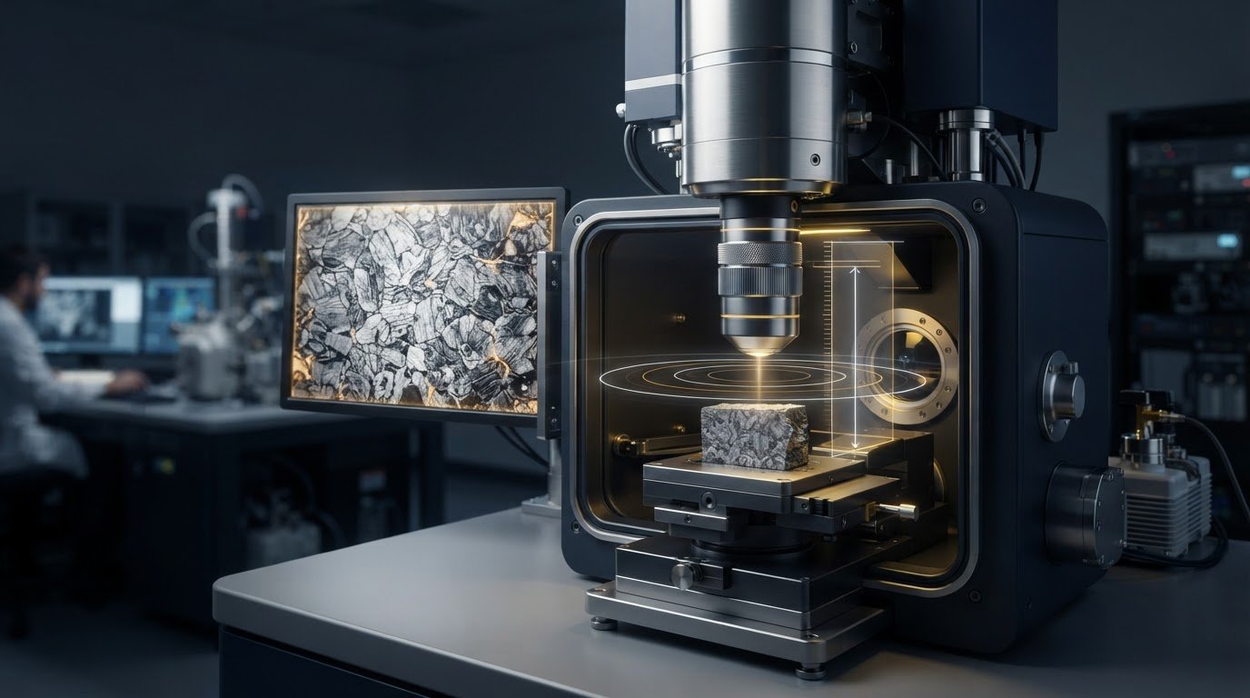
The shortest working distance isn’t automatically the best choice for an SEM image. Reducing it may support finer imaging conditions on some instruments, but it can also affect depth of field, detector response, and clearance around the sample. That trade-off is why working distance optimization in SEM should start with the imaging task, not a universal target.
If changing the distance has produced inconsistent results, the cause may involve more than working distance alone. Image quality depends on the interaction between working distance, sample geometry, detector position, and instrument design. This guide explains how working distance can influence resolution, depth of field, signal collection, and sample clearance. It also provides a repeatable way to compare settings and identify when manufacturer documentation or SEM support can help translate general principles into instrument-specific practice.
Key Takeaways
- Choose working distance according to the imaging goal. The shortest setting isn’t automatically best for every specimen or detector arrangement.
- Compare candidate settings for fine detail, depth of field, signal collection, and clearance on your specific sample.
- For reliable working distance optimization in sem, change one setting at a time while keeping key imaging conditions constant.
- Before adjusting instrument-specific settings, consult the manufacturer’s documentation and account for sample height, tilt, and possible clearance risks.
- If image quality remains inconsistent, check focus, charging, contamination, and detector setup before attributing the issue to working distance alone.
What SEM Working Distance Means, and Why It Changes Your Image
SEM working distance is the distance from the objective-lens pole piece to the specimen surface at the selected imaging position. Instruments may use different reference points or terminology, so check the microscope documentation before comparing settings across systems.
Working distance affects the geometry through which the objective lens focuses the electron beam on the specimen. Changing it also changes conditions for beam interaction and signal collection, influencing the balance among image detail, depth of field, detector response, and physical clearance. Working distance optimization in SEM is therefore specific to the task, specimen, detector, and instrument configuration.
How working distance differs from specimen height and stage position
Working distance is not the specimen’s physical height, the stage’s position, or the available space inside the chamber. However, raising or lowering the stage can change the distance between the specimen and the objective-lens pole piece, which changes the working distance. Stage movement may also change the specimen’s position relative to a detector, affecting its line of sight and the signal collected. Check the manufacturer’s documentation for the instrument’s reference point and the names used for stage controls.
Why one working distance does not suit every SEM image
Every imaging setup involves competing priorities. A shorter working distance may support finer imaging conditions on some instruments, while a longer one may provide greater depth of field in certain configurations. Neither outcome is universal. Results depend on instrument design, detector type, accelerating voltage, and specimen geometry. Detector line of sight can matter when imaging surface features or tilted samples. Tall or irregular specimens also require careful attention to clearance from the pole piece and other chamber components.
For example, a relatively flat specimen imaged for fine surface detail may call for a different compromise than a rough sample with features at different heights. Compositional imaging and tilted specimens add other considerations, including detector geometry and safe clearance. The Scanning electron microscope (SEM) overview provides broader context on SEM imaging and its characteristic depth of field. For a more detailed introduction to the technique, see these fundamental principles of scanning electron microscopy. Use these principles as a starting point, then assess working distance for the specific instrument and image required.
How Working Distance Affects Resolution, Depth of Field, and Signal
Changing working distance can alter more than the apparent sharpness of an SEM image. It changes the objective lens geometry and the specimen’s position relative to nearby detectors. The result depends on the microscope design, detector, accelerating voltage, and sample. A shorter distance may support finer imaging conditions on some systems, but it is not a universal route to a better image.
Resolution and depth of field: a task-dependent balance
Resolution describes the ability to distinguish closely spaced features. Depth of field describes how much vertical variation across a specimen can remain acceptably in focus at once. These goals can compete. A flat sample with fine surface features may call for conditions that prioritize detail, while a rough specimen may need greater depth of field to show features at different heights clearly. In some setups, a longer working distance can increase depth of field, but the effect and image quality depend on the instrument and operating conditions.
Use the feature you need to interpret as your benchmark rather than assuming a working distance will deliver a fixed resolution or focus range. Compare images at the same magnification and with other relevant settings held constant. Check the manufacturer’s documentation for suitable operating guidance.
Detector geometry, signal collection, and specimen clearance
Working distance can change the angle and unobstructed view between a specimen feature and a detector. Secondary-electron images are commonly used to examine surface topography, while backscattered-electron images can provide compositional contrast. Their signal patterns and detector requirements differ. A recess, edge, or raised feature may appear differently as stage position and detector geometry change, so judge the signal on the region of interest rather than relying on overall brightness.
Tall, tilted, or irregular specimens also require attention to clearance. Before adjusting the stage or tilt, consider the specimen’s highest point and the locations of the pole piece and detectors. Follow the instrument’s collision-prevention procedures.
Typical trade-offs to test
- Shorter distance: May support finer imaging conditions on some systems. Verify focus, detector response, and physical clearance.
- Longer distance: May provide greater depth of field in some setups. Check whether the detail and signal needed for the task remain adequate.
- Changed stage position or tilt: Can alter detector view as well as working distance. Assess signal and clearance together.
For working distance optimization in sem, compare settings against the required image outcome and the instrument’s recommendations rather than applying a universal rule. General guidance may need to be adapted to the specific instrument. Electron Optics Instruments provides SEM technical training and support.
Choosing SEM Working Distance for Different Imaging Goals
Start by defining what the image needs to show. A setting that helps reveal fine surface features may not keep an uneven specimen acceptably in focus, and a detector arrangement suited to one signal may not be ideal for another. Use this framework to identify trade-offs to test, not as a fixed prescription. Detector choice, accelerating voltage, probe conditions, sample geometry, and instrument design all influence the result.
Selecting a starting point for high-resolution surface detail
For a flat sample with small features, identify the detail you need to distinguish and choose a detector suited to the imaging task. Compare safe, manufacturer-documented working-distance positions. Refocus and assess whether the target features remain clear. Don’t assume the shortest available distance will produce the best image. Keep accelerating voltage, probe conditions, detector, scan settings, and specimen orientation consistent so that differences are more likely to reflect working distance rather than simultaneous adjustments.
Adapting the setting for topography, EDS, and tilted samples
For rough topography, consider how much vertical variation should remain in focus alongside the detail you need to resolve. With EDS, check the working geometry and clearance requirements for the specific detector configuration in the instrument documentation. Tilted or irregular specimens need particular care because stage movement can change both working distance and the specimen’s position relative to detectors or nearby components. Follow instrument procedures before changing position or tilt.
Task-based starting framework
| Imaging goal | Desired outcome | Trade-offs to evaluate |
|---|---|---|
| Fine surface detail | Resolve the features of interest | Test documented positions for focus, image detail, and detector suitability. |
| Rough topography | Show features at different heights clearly | Assess depth of field against detail and signal quality. |
| Compositional imaging or EDS | Collect a useful signal from the region of interest | Check detector geometry and configuration-specific requirements. |
| Tilted or irregular specimen | Image the target area without compromising clearance | Consider detector view, sample height, tilt, and collision risk together. |
Working distance optimization in SEM is most reliable when each comparison is tied to a defined image outcome and performed within documented operating limits. For related analytical and imaging considerations, see this guide to advanced SEM techniques. Instrument-specific training and technical support can help connect general guidance to your system through SEM training and technical support.
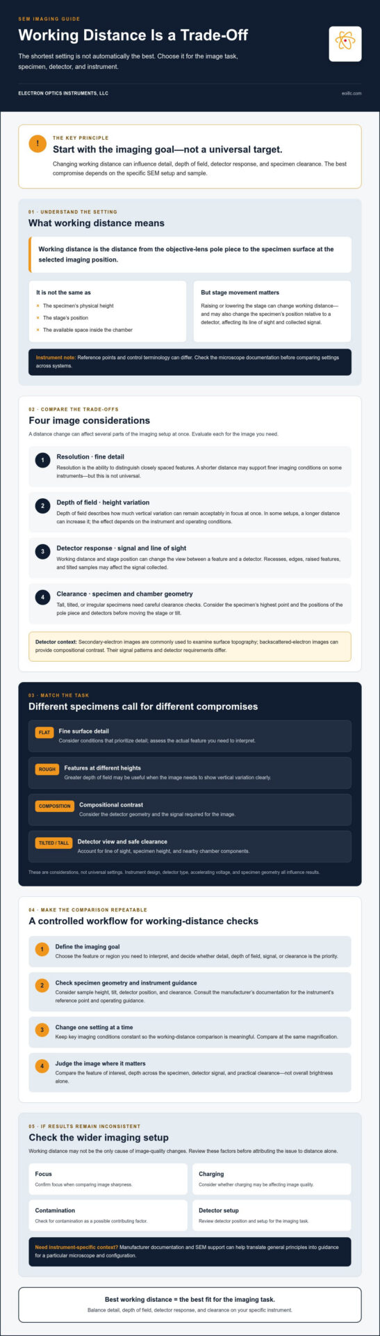
A Repeatable Workflow to Optimize Working Distance in SEM
A controlled comparison makes working distance optimization in SEM more reliable and easier to reproduce. Define what a successful image must show, then vary working distance while holding other relevant acquisition conditions steady. This helps separate its effects from changes caused by focus, detector choice, or specimen orientation.
Set up a controlled working-distance comparison
Before moving the stage, review the instrument instructions, confirm how working distance is defined, and check specimen mounting, stage limits, and safe clearance. Use only operating positions permitted by the manufacturer. If safe to do so, compare incremental changes and image the same region. If the specimen is not uniform, choose closely comparable areas.
- Define the imaging task. Identify the feature or signal you need to assess, such as fine detail, topographic variation, or a compositional feature. Set practical acceptance criteria before comparing images.
- Inspect the specimen and setup. Note sample height, shape, mounting, orientation, and any tilt. Confirm that the intended detector can view the area of interest and that stage movement will not create a clearance risk.
- Select a safe starting position. Follow the manufacturer’s recommended procedure and use an appropriate documented setup. Don’t move toward the pole piece without checking specimen height and instrument-specific limits.
- Change working distance in controlled trials. Keep accelerating voltage, probe conditions, detector, scan settings, and specimen orientation constant. Refocus as needed using the same procedure for each comparison, and record any adjustment.
- Evaluate and document the result. Assess focus, feature detail, depth of field, signal quality, charging, and clearance against the task criteria. Save representative images with the settings used.
Assess images and document the selected setting
Don’t select a setting based on apparent sharpness alone. A sharply focused feature may not be the priority if important surface heights fall out of focus, the required detector signal is weak, or the specimen lacks safe clearance. Compare images under consistent display conditions where possible, and distinguish visible differences from changes introduced during processing.
For each trial, record working distance and the instrument’s terminology, detector, accelerating voltage, probe settings, scan conditions, specimen orientation, region imaged, and relevant focus adjustments. This record helps another operator reproduce the setup and provides a baseline if the sample or imaging objective changes. For broader operating practices, consult the SEM operation guide.
Electron Optics Instruments also provides SEM training to help teams apply operating procedures to their equipment. Details are available through SEM technical training.
When to Reassess Settings or Seek SEM-Specific Support
A poor image isn’t necessarily a working-distance problem. Focus, specimen movement, charging, contamination, detector selection, and acquisition settings can all affect image quality or signal. Changing working distance without checking these factors may add variables without resolving the underlying issue.
Diagnose image problems without changing every setting at once
Use a systematic sequence of safe, reversible checks before altering stage position or other operating conditions. Preserve a known-good setup where possible, and change one variable at a time so you can identify what affects the result.
- Check focus and specimen stability. Confirm that the region of interest is in focus and that the mounted sample appears stable under the instrument’s normal operating procedure.
- Review charging and contamination indicators. Look for image behavior consistent with charging or visible evidence of contamination. Follow the manufacturer’s instructions for corrective action. Don’t attempt unfamiliar cleaning or maintenance procedures.
- Confirm detector and acquisition settings. Verify that the selected detector suits the imaging objective and that scan and probe conditions match the intended comparison.
- Revisit working distance only within documented limits. Check the instrument’s definition, recommended settings, stage limits, specimen height, and clearance before making a controlled adjustment.
Compare the result with a baseline image and note each change. Working distance can influence image formation, but it isn’t a universal remedy for low contrast, poor focus, weak signal, or other image-quality concerns.
Use instrument documentation, training, and service expertise
Pause before moving the stage if clearance is uncertain, the instrument behaves unexpectedly, or you can’t confirm the correct procedure for a detector or specimen configuration. Consult the manufacturer’s documentation for system limits, geometry, and operating recommendations. Settings from a different SEM model may not apply.
When operators need a consistent procedure for unfamiliar samples or detectors, SEM-specific training can help translate general imaging principles into instrument-specific practice. Electron Optics Instruments provides SEM training, maintenance, and repair support. The appropriate next step depends on the instrument and the issue.
Careful working distance optimization in SEM combines controlled comparisons with sound troubleshooting. If basic checks don’t explain inconsistent images, document the setup and observed behavior before seeking experienced support. That record can clarify what has already been tested.
Build a More Consistent SEM Imaging Workflow
Effective working distance optimization in sem starts with the image you need, not a universal distance target. The right setting balances resolution, depth of field, detector response, specimen geometry, and safe clearance. Compare documented settings systematically, keep other acquisition conditions stable, and record the setup alongside representative images so results can be repeated.
If image quality remains inconsistent, check focus, charging, contamination, and detector configuration before assuming working distance is the cause. Use manufacturer documentation to confirm instrument-specific limits and recommendations, especially when stage position, tilt, or sample height affects clearance.
Electron Optics Instruments has more than 30 years of SEM industry experience and provides SEM training, maintenance, and repair support. To connect general optimization principles with your lab’s equipment and operating practices, explore SEM equipment and support from Electron Optics Instruments.
A controlled comparison process and instrument-specific guidance can help your team make working-distance decisions with greater confidence and consistency.
Frequently Asked Questions
What is working distance in an SEM?
Working distance is generally the distance between the objective-lens pole piece and the specimen surface at the imaging position. The exact reference point and control terminology can vary by instrument, so check the manufacturer’s documentation before comparing values between systems. Working distance is distinct from specimen height or stage position, although moving the stage can change the distance and the specimen’s geometry relative to a detector.
Is a shorter working distance always better for SEM resolution?
No. A shorter working distance isn’t always better for SEM resolution. On some systems, it may support imaging conditions suited to finer detail, but the outcome depends on instrument design, accelerating voltage, probe conditions, detector, and specimen. A short setting may also reduce clearance or change detector geometry. Compare documented, safe settings using the image feature you need to resolve, while keeping other acquisition conditions consistent.
How does working distance affect depth of field in SEM?
Working distance can influence how much height variation across a specimen remains acceptably in focus. In some imaging setups, a longer distance may increase depth of field, but the effect depends on the instrument and operating conditions. For a flat sample, fine detail may be the priority. For a rough surface, keeping features at different heights in focus may matter more. Evaluate the actual specimen rather than relying on a universal rule.
What working distance should I use for SEM imaging?
Choose a working distance based on the image objective, specimen geometry, detector arrangement, and your microscope’s documented operating guidance. No single setting suits every SEM image. For working distance optimization in sem, define the outcome you need, such as resolving surface detail or imaging uneven topography, then compare permitted settings while holding other relevant conditions constant. Record the selected distance and associated acquisition settings so the setup can be repeated.
Can changing working distance improve EDS results?
Changing working distance can affect EDS measurement geometry, but it doesn’t guarantee improved results. The specimen’s position and orientation relative to the EDS detector can influence its view of the analysis area and the signal collected. Check the manufacturer’s recommendations for the specific SEM and EDS configuration, including clearance and geometry requirements. If you compare settings, keep other relevant conditions stable and assess results against the analytical objective.
What should I do if changing working distance does not improve my SEM image?
Check other likely contributors before changing more settings. Confirm focus and specimen stability, review signs of charging or contamination, and verify detector selection and acquisition conditions. Change one variable at a time and preserve a known-good setup where possible. Consult the instrument documentation before moving the stage, especially if clearance is uncertain or behavior is unusual. If routine checks don’t resolve the issue, contact Electron Optics Instruments to discuss SEM training, maintenance, or repair support.