
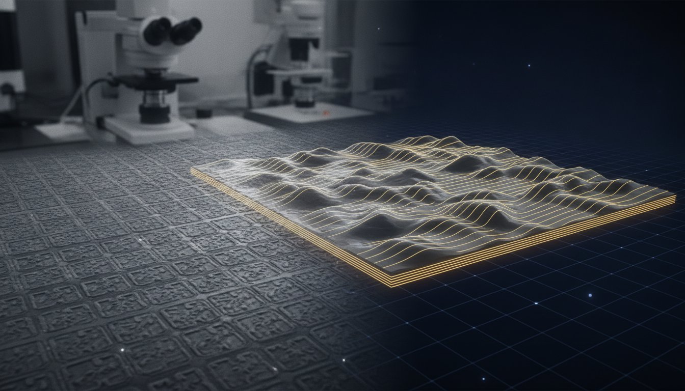
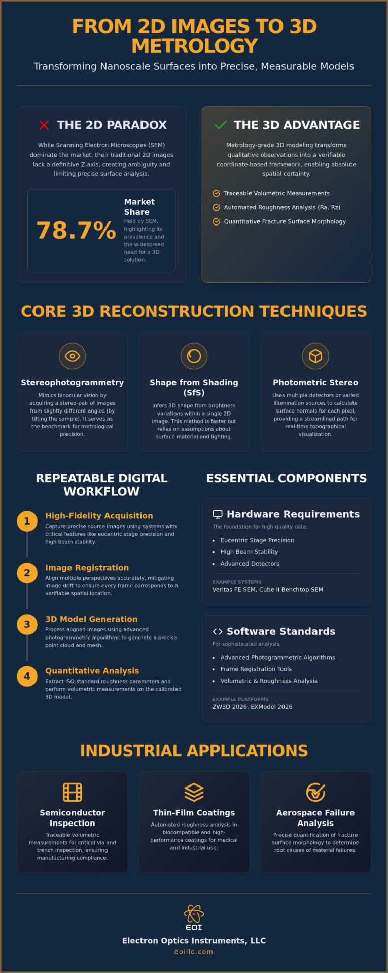
The traditional reliance on two-dimensional scanning electron micrographs often leaves researchers grappling with a fundamental paradox; the more detail we capture in a flat image, the more we realize the limitations of our depth perception at the nanoscale. While SEM continues to dominate the microscopy market with a 78.7% share, the inherent ambiguity of surface topography remains a significant hurdle for engineers requiring precise volumetric data. You likely understand the difficulty of measuring surface roughness when your primary data source lacks a definitive z-axis. This guide establishes that creating 3d models from sem images is no longer a speculative endeavor but a metrology-grade reality achieved through the rigorous integration of electron optics and advanced photogrammetric algorithms.
By mastering these principles, you’ll gain a repeatable workflow for transforming standard grayscale outputs into accurate topographical reconstructions. We will evaluate the hardware requirements necessary for high-fidelity data acquisition, focusing on the capabilities of advanced systems like the Veritas FE SEM or the Cube II Benchtop SEM. This analysis also previews the latest software standards found in ZW3D 2026 and EXModel 2026, providing you with the technical framework to perform sophisticated volumetric and roughness analysis. We’ll move beyond simple visualization to explore a future where the synergy of hardware and software delivers absolute spatial certainty.
Key Takeaways
- Differentiate between stereophotogrammetry and Shape from Shading to select the most effective reconstruction methodology for specific topographical requirements.
- Identify the critical hardware specifications, such as eucentric stage precision and beam stability, required to ensure high-fidelity data acquisition.
- Establish a repeatable digital workflow for creating 3d models from sem images that effectively mitigates image drift and ensures accurate frame registration.
- Apply quantitative 3D profiling to specialized industrial sectors, including semiconductor inspection and the advanced failure analysis of fracture surfaces.
- Master the transition from subjective depth perception to metrology-grade volumetric analysis to achieve superior precision in nanoscale surface measurements.
The Evolution from 2D Micrographs to 3D Topographical Models
Scanning electron microscopy has long provided unparalleled lateral resolution, yet its reliance on two-dimensional projections creates a significant analytical void. A standard micrograph represents a 2D intensity map where depth is merely inferred through shading and human perception. This inherent limitation complicates the objective assessment of complex nanostructures. By 2026, the industry has pivoted toward creating 3d models from sem images to satisfy increasingly rigorous metrological standards in semiconductor manufacturing and advanced materials science. True 3D reconstruction transcends visual aesthetics, transforming qualitative observations into a coordinate-based framework where every pixel corresponds to a verifiable spatial location.
Modern industrial compliance now demands more than high-resolution imagery. As the global electron microscopy market is projected to reach USD 10.11 billion by 2034, the integration of Core Techniques for 3D Surface Reconstruction has become essential for validating topographical specifications. 2026 standards prioritize data that supports:
- Traceable volumetric measurements for semiconductor via and trench inspection.
- Automated roughness analysis in biocompatible thin-film coatings.
- Fracture surface morphology quantification in aerospace failure analysis.
There is a critical distinction between ‘pseudo-3D’ visualization, which uses software to tilt a flat image, and metrology-grade 3D modeling. The latter requires the precise alignment of multiple perspectives to generate a point cloud with traceable accuracy. Achieving this level of precision is fundamental when creating 3d models from sem images for high-stakes quality control. Without these rigorous protocols, a model is merely an artistic representation rather than a reliable engineering asset.
The Physics of Topographical Contrast
Secondary electron (SE) emission is highly sensitive to the geometric orientation of the sample surface relative to the detector. When the primary electron beam strikes a tilted surface, the interaction volume remains closer to the surface, allowing a higher yield of secondary electrons to escape and reach the detector. This phenomenon, coupled with the ‘edge effect’ where sharp boundaries appear brighter due to increased emission area, provides the raw signal for topographical interpretation. Topographical contrast is the variation in signal intensity based on local surface slope.
Quantitative vs. Qualitative 3D Analysis
While qualitative 3D analysis serves a vital role in visualizing surface morphology for technical reports, it lacks the rigor required for industrial process control. Quantitative analysis involves extracting ISO-standard roughness parameters, such as Ra and Rz, directly from the reconstructed mesh. This transition requires meticulous Z-axis calibration within the electron optics system. Without a verified vertical scale, a 3D model remains a mere illustration rather than a tool for scientific measurement. High-end systems like the Veritas Series SEM or Veritas FE SEM provide the stability necessary to move from simple imaging to true topographical metrology.
Core Techniques for 3D Surface Reconstruction in Electron Microscopy
The pursuit of metrological accuracy in creating 3d models from sem images relies on three primary technical pillars: stereophotogrammetry, Shape from Shading (SfS), and photometric stereo. Each method offers distinct advantages in resolution and processing speed. Stereophotogrammetry remains the benchmark for precision, while multi-detector systems provide a streamlined path for real-time topographical visualization. Establishing a robust protocol for creating 3d models from sem images requires a deep understanding of how electron-sample interactions manifest as topographical data.
Stereophotogrammetry and the Parallax Effect
This technique mimics human binocular vision by acquiring a stereo-pair of micrographs at two different tilt angles. By measuring the lateral displacement, or parallax, of identical surface features between the two frames, software can mathematically derive the relative height of each pixel. A tilt angle between 5° and 10° is typically optimal; insufficient tilt reduces depth resolution, while excessive tilt introduces significant sample shadowing and obscures re-entrant features. While highly accurate, this method is computationally intensive and requires precise eucentric stage control to maintain the same field of view during tilting.
Multi-Detector BSE Topography
Utilizing four-quadrant Backscattered Electron (BSE) detectors represents a shift toward more integrated, real-time 3D data acquisition. By capturing directional signals from each quadrant simultaneously, the system can reconstruct geometry based on the intensity ratios between detectors. This approach is particularly effective for relatively flat samples with subtle height variations, such as polished metallurgical cross-sections or semiconductor wafers. It’s a reliable method for high-volume inspection where throughput is a priority and the sample doesn’t permit extensive tilting.
Shape from Shading (SfS) offers an alternative for scenarios where tilting is impractical or impossible. This method interprets the grayscale intensity of a single micrograph as a function of the local surface slope. Recent advancements, such as the Purdue University research on single-image 3D reconstruction, have significantly improved the reliability of this approach for nanostructures. However, SfS often requires meticulous calibration of the detector’s response function to avoid artifacts. It’s essentially a trade-off between acquisition speed and topographical fidelity.
Choosing the appropriate technique depends on the specific requirements of the analytical task. Stereophotogrammetry provides the highest absolute accuracy for complex 3D structures, whereas BSE-based topography offers superior speed for high-throughput environments. For those seeking the hardware stability required for these advanced workflows, exploring Veritas Series SEM systems ensures your laboratory is equipped with the necessary precision for reliable topographical data.
Hardware Considerations: Optimizing Your SEM for 3D Data Acquisition
High-fidelity topographical reconstruction is an engineering challenge that begins with the physical stability of the microscope. While software algorithms are increasingly sophisticated, they cannot compensate for hardware-induced artifacts or mechanical drift. A high-precision eucentric stage is the primary requirement for successful data acquisition. It ensures that the sample remains at the center of the electron beam’s focal plane during tilting maneuvers, which is vital for maintaining a consistent field of view when creating 3d models from sem images. Without eucentricity, the sample will shift laterally and vertically, complicating the image registration process.
Beam stability directly impacts the pixel-to-pixel correlation between stereo pairs. Any fluctuations in the electron probe during acquisition introduce spatial errors that manifest as noise or “spikes” in the final 3D mesh. Similarly, detector sensitivity and geometry play a pivotal role in signal quality. Low-noise detectors provide the clean signal necessary for the grayscale gradient analysis used in Shape from Shading. Integrating EDS (Energy Dispersive Spectroscopy) systems allows for the development of “4D models,” where topographical geometry is overlaid with precise chemical mapping. This holistic approach is essential for modern volumetric analysis using SEM photogrammetry, particularly in complex metallurgical failure analysis where surface chemistry and morphology are inextricably linked.
Benchtop vs. Floor-Standing SEMs for 3D Modeling
The Cube II Benchtop SEM has revolutionized automated 3D workflows by offering high performance in a compact footprint that fits standard laboratory environments. While floor-standing units like the Veritas FE SEM are generally preferred for sub-micron topography due to their superior resolution and field emission sources, modern benchtop systems now include sophisticated vacuum controls. These advanced vacuum systems maintain the high signal-to-noise ratios required for clean reconstructions by minimizing carbon contamination and beam scattering. For researchers creating 3d models from sem images, the choice between these platforms often hinges on the required lateral resolution and the complexity of the sample’s features.
Calibration Standards for 3D Metrology
Metrological integrity depends on the consistent use of NIST-traceable lateral and vertical standards. Researchers must meticulously correct for scan distortion and electromagnetic interference to ensure that the digital twin matches the physical reality. Calibration ensures that the software’s interpretation of pixel displacement corresponds to actual physical dimensions. 3D accuracy is fundamentally limited by the SEM’s lateral resolution and beam spot size. By establishing these rigorous hardware protocols, laboratories can ensure that their 3D models transition from simple visual aids to reliable engineering assets capable of supporting critical industrial decisions.
The Digital Workflow: Processing SEM Images into Metrology-Grade 3D Models
The successful transition from raw data to a verifiable topographical asset requires a methodical digital sequence that preserves the spatial integrity of the electron signal. When creating 3d models from sem images, the workflow begins with high-overlap acquisition, where researchers typically target 60% to 80% redundancy between frames. This overlap is essential for the correlation algorithms that identify homologous points across the dataset. High-quality acquisition also demands a low-noise environment, often achieved through slower scan speeds or frame averaging, to ensure that the resulting grayscale gradients are representative of actual surface geometry rather than electronic interference.
Once you’ve acquired the micrographs, the alignment and registration phase corrects for inevitable lateral and rotational shifts. This step precedes the generation of a dense point cloud, where sophisticated matching algorithms calculate depth based on the parallax principles discussed in previous sections. The final stages involve surface meshing and texturing to create a continuous 3D manifold. Post-processing then allows for the application of noise filters and the execution of precise volumetric measurements. This rigorous approach ensures that the final model isn’t just a visual representation but a metrological tool capable of supporting industrial quality control.
Overcoming the SEM Drift Challenge
Thermal and electronic drift represent the most significant obstacles to accuracy in 3D reconstruction. Even microscopic shifts during the acquisition of a stereo pair can lead to pixel-to-pixel mismatches, resulting in “ghosting” or distorted geometry in the final mesh. Mastering SEM operation in 2026 involves utilizing active drift compensation techniques, such as real-time beam tracking or automated image stabilization software. These tools identify stationary features and adjust the scan field to maintain a consistent coordinate system throughout the imaging session. If drift isn’t mitigated at the source, software-based post-acquisition stabilization becomes a mandatory prerequisite before model building can commence.
Selecting the Right Reconstruction Software
The choice of software is a critical decision point for any laboratory. While general photogrammetry tools are widely available, they often struggle with the near-orthographic projection of an electron beam, which differs fundamentally from the perspective projection of standard optical lenses. Specialized SEM metrology software offers auto-tilt detection and precise Z-axis scaling tailored to the specific physics of electron optics. For high-throughput environments, batch processing capabilities are essential to maintain efficiency across large datasets. If your laboratory requires the highest level of precision for creating 3d models from sem images, investing in advanced SEM systems and technical support ensures that your digital workflow remains as rigorous as your hardware protocols.
Industrial Applications and the Future of 3D SEM Analysis
The transition from laboratory-scale research to industrial-grade metrology has redefined the return on investment for high-resolution microscopy. While academic institutions have long utilized topographical data for material characterization, modern manufacturing sectors now rely on creating 3d models from sem images to achieve unprecedented levels of process control. This shift is particularly evident in the semiconductor industry, where the 3D profiling of vias and trenches is essential for validating the integrity of high-aspect-ratio features. Similarly, in the field of tribology, the ability to quantify wear patterns on industrial components with nanometer-scale precision allows engineers to predict component lifespan and optimize lubricant performance with a degree of accuracy that 2D imaging simply cannot facilitate.
3D SEM in Failure Analysis
In the high-stakes environment of aerospace and automotive engineering, identifying the precise point of origin in mechanical failures is a critical requirement. 3D models provide a comprehensive view of fracture surface morphology, allowing forensic engineers to distinguish between fatigue, brittle fracture, and ductile overload. By creating 3d models from sem images, analysts can quantify the exact volume of material lost to corrosion or erosion, providing a data-driven foundation for structural integrity assessments. Integrating these topographical reconstructions with advanced SEM techniques ensures that root cause identification is based on verifiable spatial data rather than subjective visual interpretation. This level of meticulousness is fundamental for maintaining international safety standards and reducing the risk of catastrophic system failures.
Emerging Trends: AI and Automated Metrology
The future of scanning electron microscopy lies in the seamless integration of artificial intelligence and real-time visualization. Machine learning algorithms are currently being deployed to reduce stochastic noise in low-vacuum 3D imaging, allowing for the reconstruction of non-conductive or sensitive samples without the need for extensive coating. This advancement streamlines the workflow for high-throughput laboratories by enabling automated pass/fail inspection protocols based on 3D surface parameters. Looking ahead, the integration of real-time augmented reality (AR) will allow operators to navigate complex topographical landscapes as they are being scanned, effectively bridging the gap between data acquisition and analytical insight.
EOI remains at the forefront of this technological transformation, supporting the transition to automated 3D workflows through the Veritas series of microscopes. Systems like the Veritas Ultra SEM and Veritas HR SEM provide the requisite beam stability and detector sensitivity to support AI-driven reconstruction efforts. As the industry moves toward a more autonomous analytical model, the synergy between advanced hardware and intelligent software will continue to push the boundaries of what is possible in nanoscale metrology. This commitment to innovation ensures that our partners are equipped with the technical prowess necessary to lead in an increasingly complex global industrial landscape.
Advancing Nanoscale Metrology Through Digital Transformation
The integration of topographical data into the analytical workflow represents a fundamental shift in how professionals perceive and measure the nanoscale. Mastering the process of creating 3d models from sem images allows your laboratory to move beyond visual aesthetics toward a regime of metrology-grade accuracy. This transition is underpinned by a rigorous understanding of eucentric stage stability and the application of advanced correlation algorithms. As the industry moves toward AI-driven reconstruction, maintaining high-fidelity hardware standards remains the primary prerequisite for scientific validity.
With over 30 years of electron optics expertise, EOI provides the technical foundation necessary for these sophisticated reconstructions. We serve as the sole US distributor for EmCraft SEMs and offer comprehensive service and training for all major SEM brands to ensure your equipment operates at peak performance. We invite you to request a technical consultation on 3D SEM capabilities for your laboratory to discuss how these advancements can enhance your specific industrial applications. Achieving absolute spatial certainty in your topographical analysis isn’t just a goal; it’s a measurable reality.
Frequently Asked Questions
Can I create 3D models from SEM images without tilting the sample?
Yes, you can utilize Shape from Shading (SfS) or multi-quadrant Backscattered Electron (BSE) detectors to generate topographical data without tilting. While stereophotogrammetry remains the benchmark for absolute accuracy, these alternative methods interpret signal intensity or directional emission to derive height information. This approach is particularly advantageous for samples where mechanical tilting is restricted or could introduce significant shadowing.
How many images are required for a high-quality 3D SEM reconstruction?
A minimum of two images is required for basic stereo-pair reconstruction, though high-fidelity models often utilize larger datasets. For complex 3D photogrammetry, capturing between 12 and 36 images with substantial overlap ensures a denser point cloud. When creating 3d models from sem images, maintaining a 60% to 80% overlap between frames is critical for the correlation algorithms to accurately identify matching surface features.
What is the typical vertical resolution achievable in 3D SEM modeling?
Vertical resolution in 3D SEM modeling is fundamentally linked to the microscope’s lateral resolution and the precision of the tilt angle. In optimized systems like the Veritas Series SEM, vertical resolution can reach the nanometer scale, often matching the lateral spot size of the electron beam. Achieving this level of precision requires meticulous calibration and a stable vacuum environment to minimize signal fluctuations.
Is specialized software required, or can I use open-source photogrammetry tools?
While open-source photogrammetry tools like Blender 5.1 or FreeCAD 1.1 can process micrographs, specialized SEM metrology software is highly recommended for industrial applications. These professional platforms account for the orthographic projection of the electron beam, which differs from the perspective projection of standard optical cameras. Specialized software also includes automated Z-axis scaling and NIST-traceable calibration tools that open-source alternatives often lack.
How do I calibrate the Z-axis for accurate 3D height measurements?
Calibrating the Z-axis requires the use of NIST-traceable lateral and vertical standards, such as certified step-height samples. By measuring a known vertical dimension under specific tilt and magnification settings, you can establish a calibration factor that converts pixel parallax into physical units. This process is essential for creating 3d models from sem images that support quantitative volumetric or roughness analysis.
Can 3D models be generated from Backscattered Electron (BSE) images?
Yes, 3D models are frequently generated from Backscattered Electron (BSE) images, especially when utilizing a four-quadrant detector system. BSE signals are highly sensitive to surface orientation, allowing the system to reconstruct topography by comparing the intensity ratios between different detector quadrants. This method is particularly effective for metallurgical samples where compositional contrast and topographical data must be analyzed simultaneously.
What are the most common artifacts in 3D SEM reconstruction and how can they be avoided?
The most prevalent artifacts include shadowing, image drift, and electronic noise, all of which can lead to distortions in the 3D mesh. Shadowing is avoided by optimizing the tilt angle and detector positioning, while drift is mitigated through the use of high-precision eucentric stages. Proper beam current selection and frame averaging are necessary to maintain the high signal-to-noise ratio required for a clean surface manifold.
How does the Cube II Benchtop SEM facilitate 3D imaging for small labs?
The Cube II Benchtop SEM brings advanced topographical capabilities to smaller laboratories by integrating high-performance electron optics into a compact, automated platform. It features sophisticated vacuum controls and stable stages that simplify the acquisition of high-overlap stereo pairs. This system allows labs to perform metrology-grade 3D analysis without the extensive infrastructure requirements of traditional floor-standing microscopes.