
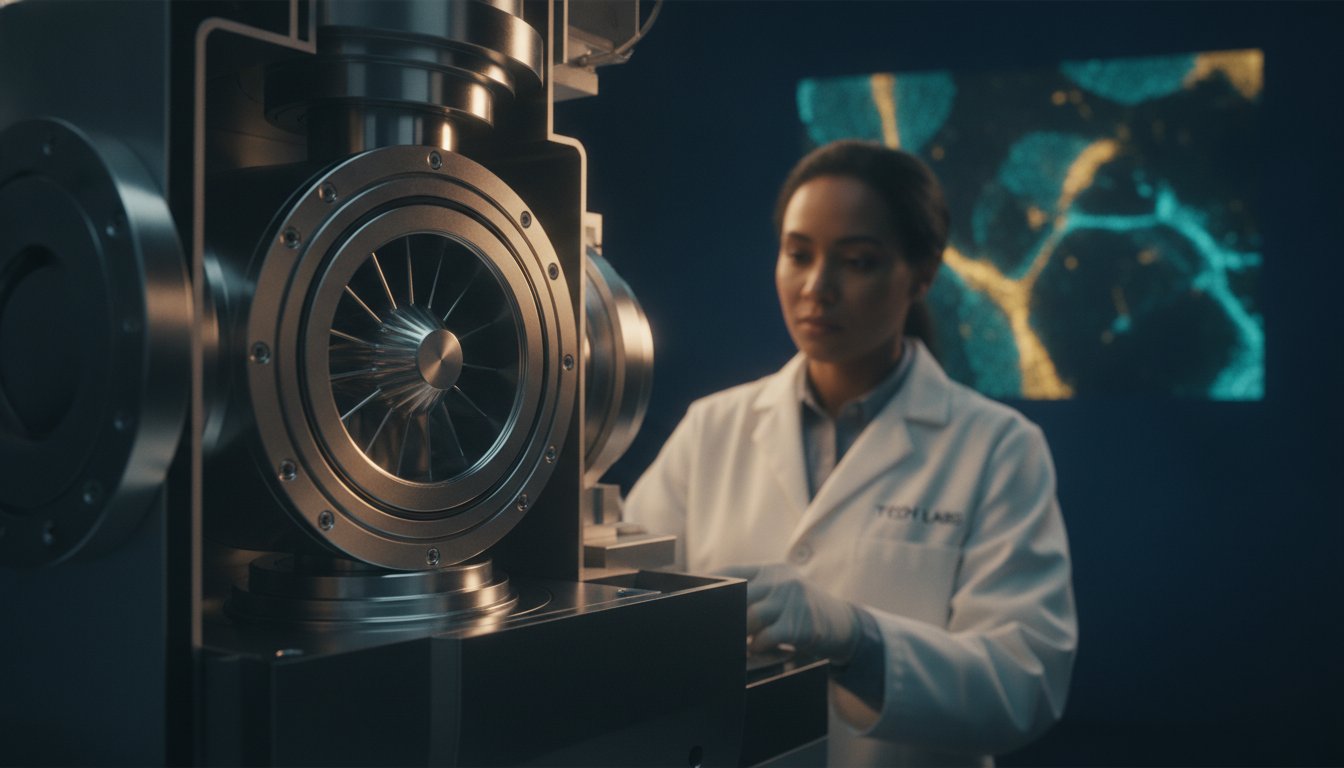
A single compromised O-ring, a marginal pressure reading dismissed as within tolerance, a turbomolecular pump running warmer than usual: these are the quiet precursors to the kind of catastrophic vacuum failure that halts research programs and burns through filaments at a rate that no maintenance budget can comfortably absorb. Every SEM vacuum system failure has a traceable origin, and understanding that origin before it becomes an emergency is precisely what separates high-throughput imaging facilities from those perpetually contending with downtime.
If you’ve watched your image resolution degrade without a clear explanation, or replaced filaments far more frequently than manufacturer guidance suggests, you’re already living with the consequences of vacuum instability. These aren’t isolated equipment quirks; they’re diagnostic signals embedded in the physics of how your roughing and turbomolecular pump stages interact under real operating conditions.
This guide delivers a rigorous, technically grounded examination of modern SEM vacuum architecture, covering the synergy between pump stages, the preventative maintenance disciplines that protect electron optics, and the specific design considerations that distinguish high-performance systems from those that underperform. What follows is built for the professionals who need precision, not approximations.
Key Takeaways
- A properly engineered sem vacuum system is the foundational determinant of electron beam stability, image resolution, and filament longevity — understanding its architecture allows you to diagnose performance degradation before it escalates into costly downtime.
- The sequential relationship between roughing and turbomolecular pump stages is not merely mechanical convention; it is a precisely calibrated pressure cascade where failures in early stages compound exponentially through the entire optical column.
- Vacuum leaks and instability manifest through identifiable image artifacts and pump-down anomalies long before catastrophic failure occurs, giving informed operators a critical window for intervention.
- Preventative maintenance disciplines — particularly O-ring inspection and scheduled pump servicing — represent the highest-return investment available for protecting electron optics and sustaining throughput capacity.
- Purpose-built platforms such as the Cube II Benchtop SEM and the Veritas FE SEM demonstrate how integrated vacuum design directly translates into operational reliability and imaging performance across divergent application demands.
The Fundamental Role of Vacuum Systems in Scanning Electron Microscopy
Electrons don’t behave well in air. At atmospheric pressure, a beam of electrons traveling from gun to specimen would scatter almost immediately upon encountering nitrogen and oxygen molecules, rendering any meaningful imaging impossible. The sem vacuum system exists to eliminate this interference entirely, creating the controlled pressure environment within which coherent electron optics can function. Understanding why this matters at a physical level transforms how operators interpret performance data and respond to early warning signals.
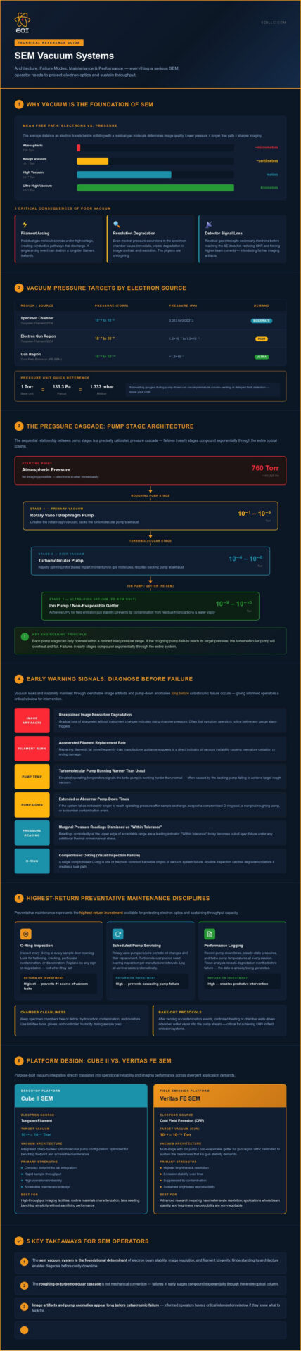
The governing principle here is mean free path: the average distance an electron travels before colliding with a residual gas molecule. At atmospheric pressure (approximately 760 Torr), mean free path for electrons is measured in micrometers. Reduce the chamber pressure to 10-4 Torr and that distance extends to meters, allowing the beam to traverse the full column length without significant scattering. This is why even modest pressure excursions in the specimen chamber produce immediate, visible degradation in image contrast and resolution. The physics are unforgiving. A broader understanding of scanning electron microscope vacuum requirements illustrates how fundamentally the entire electron optical pathway depends on maintaining this molecular clearance at every stage.
Arcing represents a separate and financially consequential risk. In the electron gun assembly, high voltages are applied across relatively small gaps. Residual gas molecules at insufficient vacuum levels become ionized under these conditions, creating conductive pathways that produce electrical discharge. A single arcing event can destroy a tungsten filament instantly and, in more severe cases, damage condenser lens coatings or detector electronics. The replacement cost of consumables alone makes vacuum integrity a direct line item in operational budgets, not an abstract engineering concern.
Secondary electron detector efficiency compounds this further. SE detectors rely on a clean electrostatic collection field to attract low-energy secondary electrons emitted from the specimen surface. Residual gas molecules intercept and scatter these electrons before they reach the detector, reducing signal-to-noise ratio and forcing operators to compensate with longer dwell times or higher beam currents, both of which introduce their own imaging artifacts.
Vacuum Requirements Across Different SEM Sources
Not all electron sources impose identical vacuum demands. Tungsten filament SEMs typically operate at specimen chamber pressures in the range of 10-4 to 10-5 Torr, a comparatively accessible target for rotary-backed turbomolecular pump configurations. Field emission SEMs operate under substantially more stringent constraints: the gun region of a cold field emission source requires pressures approaching 10-9 to 10-10 Torr to prevent tip contamination and emission instability. The Veritas FE SEM is engineered to meet precisely these demands, with vacuum architecture calibrated to sustain the cleanliness that field emission gun stability requires. Residual hydrocarbons and water vapor, even at trace concentrations, adsorb onto emission tips and degrade brightness reproducibility over time.
Common Vacuum Pressure Units in 2026 Labs
Pressure unit literacy matters more than it might appear. Modern SEM interfaces display readings in Torr, Pascal (Pa), or millibar (mbar) depending on instrument origin and regional convention, and misreading a gauge during pump-down can lead to premature column venting or delayed fault detection. The relationships are fixed: 1 Torr equals approximately 133.3 Pa and 1.333 mbar. Typical operating targets break down as follows:
- Specimen chamber: 10-4 to 10-6 Torr (0.013 to 0.00013 Pa) for tungsten source instruments
- Electron gun region (tungsten): 10-5 to 10-6 Torr
- Electron gun region (FE sources): 10-9 Torr and below
Digital vacuum gauges on current-generation instruments typically display real-time readings from multiple ion and Pirani gauge positions simultaneously, allowing operators to identify pressure differentials between pump stages that signal developing leaks or pump degradation well before imaging performance deteriorates.
Anatomy of an SEM Vacuum System: Mechanical and High-Vacuum Stages
Achieving the molecular clearance conditions described in the previous section doesn’t happen in a single step. Every functional sem vacuum system operates as a staged pressure cascade, where each pump technology hands off to the next at a pressure threshold it’s physically incapable of crossing alone. Understanding this handoff architecture is what separates operators who respond intelligently to pump-down anomalies from those who wait for catastrophic failure to explain the problem.
The journey from atmospheric pressure (760 Torr) to the operating pressures required for electron optics spans roughly nine orders of magnitude. No single pump technology bridges that range. The engineering solution is sequential staging: a mechanical roughing pump establishes the intermediate vacuum that a turbomolecular pump requires to operate safely, and only once that backing pressure is confirmed does the high-vacuum stage engage. This interdependency is the central architectural fact of SEM vacuum design, and it’s where most preventable failures originate.
The Roughing Stage: Rotary Vane and Scroll Pumps
Rotary vane pumps have served as the workhorse roughing stage for decades, reliably evacuating chambers from atmosphere to the 10-2 to 10-3 Torr range where turbomolecular pumps can begin operating. Their limitation in precision environments is well-documented: oil-sealed rotary vane pumps introduce hydrocarbon vapor backstreaming risk, particularly during startup and shutdown transitions, which can contaminate specimen chambers and degrade detector performance over time.
Dry scroll pumps have become the preferred alternative in cleanroom-adjacent and contamination-sensitive installations. Operating without process oil, scroll pumps eliminate backstreaming risk entirely while achieving comparable roughing performance. Their mechanical architecture, two interleaved spiral scrolls compressing gas toward a central outlet, also produces lower vibration signatures than rotary vane designs. Vibration isolation matters considerably in benchtop SEM configurations: mechanical pump vibration transmitted through inadequately isolated connections introduces a persistent, low-frequency image blurring that operators sometimes misattribute to beam instability or specimen charging.
Routine maintenance for mechanical roughing stages centers on several disciplines:
- Oil-sealed rotary vane pumps: Oil condition monitoring and scheduled oil changes at manufacturer-specified intervals, inlet filter inspection, and shaft seal integrity checks
- Dry scroll pumps: Tip seal replacement at prescribed service intervals, exhaust filter condition assessment, and bearing inspection
- Both types: Exhaust line integrity verification to prevent oil mist or particulate contamination of laboratory environments
Deferred roughing pump maintenance is a particularly insidious failure mode because degraded mechanical pump performance manifests first as extended pump-down times rather than immediate imaging artifacts, giving operators a misleading sense that the system is still functional.
The High-Vacuum Stage: Turbomolecular Pump Performance
Turbomolecular pumps achieve high vacuum through momentum transfer rather than compression. Rotating blade stages spinning at speeds typically between 60,000 and 90,000 RPM impart directional momentum to residual gas molecules, driving them toward the exhaust where the backing pump removes them. This mechanism is highly effective from approximately 10-2 Torr down to 10-8 Torr or beyond, covering the full operating range required by both tungsten filament and field emission SEM configurations. A thorough treatment of SEM vacuum system principles and operation from Carleton College’s SERC platform provides useful foundational context for understanding why these pressure thresholds are non-negotiable for coherent electron beam formation.
Backing pressure is the critical dependency. Turbomolecular pumps require the mechanical roughing stage to maintain outlet pressures below a defined threshold, typically in the range of 0.1 Torr or lower, to sustain efficient operation. When backing pressure rises above this threshold due to roughing pump degradation, turbomolecular pump rotor loading increases, bearing temperatures rise, and pump longevity decreases measurably. This is the cascade failure pathway that makes roughing pump health a direct determinant of high-vacuum stage lifespan.
Benchtop SEM configurations present specific thermal and acoustic management challenges. Turbomolecular pumps generate heat through bearing friction and motor operation; in compact instrument enclosures, this heat must be actively managed to prevent thermal drift in surrounding electronics. Magnetic bearing turbomolecular pumps, increasingly common in current-generation benchtop instruments, reduce both noise output and thermal load compared to conventional ball-bearing designs while also eliminating the lubrication maintenance requirements that ball-bearing configurations demand. For facilities evaluating platform reliability, understanding how vacuum architecture is integrated at the instrument design level, rather than treated as an afterthought, is a meaningful differentiator. Exploring the Cube II Benchtop SEM’s integrated approach to these engineering challenges at Electron Optics Instruments provides a practical reference point for what purposeful vacuum integration looks like in a production-grade benchtop platform.
Identifying and Troubleshooting SEM Vacuum Failures
Vacuum failures rarely announce themselves dramatically. They accumulate quietly, expressing themselves first through subtle operational anomalies that operators too often attribute to specimen condition or beam alignment before the actual source is identified. Developing a structured diagnostic framework for your sem vacuum system transforms these ambiguous signals into actionable intelligence before they escalate into column damage or extended downtime.
Extended pump-down times are frequently the earliest measurable indicator. If a chamber that previously reached operating pressure in a predictable window now requires significantly longer, the cause is almost always one of three things: a developing leak at a sealing interface, degraded roughing pump performance, or outgassing from a contaminated specimen or chamber surface. Distinguishing between these requires methodical gauge analysis rather than assumption.
Image artifacts provide a parallel diagnostic channel. Vacuum instability produces characteristic signatures that differ meaningfully from other image quality issues:
- Random horizontal banding or streaking: Often correlates with pressure fluctuations in the specimen chamber, particularly during pump-down transitions
- Gradual image drift without specimen movement: Frequently indicates residual gas molecule interactions with the beam, causing inconsistent deflection across the scan field
- Elevated background noise with reduced contrast: Characteristic of secondary electron signal degradation from residual gas scattering, as described in the previous section
- Intermittent brightness fluctuations: Can indicate gun region pressure excursions, particularly in field emission configurations where gun vacuum stability is most critical
Outgassing deserves particular attention because it’s frequently operator-induced rather than equipment-driven. Hydrated biological samples, porous geological specimens, and contaminated stubs all introduce volatile compounds into the chamber environment at rates that overwhelm pump capacity. A specimen that appears dry to visual inspection may carry sufficient adsorbed moisture to destabilize chamber pressure for extended periods. Proper sample preparation protocols, including adequate desiccation and sputter coating where appropriate, are not optional refinements; they’re fundamental to vacuum integrity.
Gauge-based leak isolation follows a logical sequence. Monitoring the differential between the chamber gauge and the column gauge during pump-down reveals whether a pressure anomaly is localized to the specimen stage region or propagating from the column itself. A chamber pressure that stabilizes normally while column pressure remains elevated points toward the gun assembly or aperture interfaces rather than the door seal or stage mechanism.
External vs. Internal Leaks
External leaks at O-ring interfaces are the most common source of vacuum degradation in operational SEMs. Door seals, viewport gaskets, and specimen exchange port seals are all subject to compression set and micro-cracking over time, particularly in facilities where thermal cycling is frequent. Visual inspection alone is insufficient; O-rings that appear intact under normal lighting can harbor micro-cracks that only manifest under the low-pressure differential of actual pump-down conditions.
Helium leak detection provides the most reliable methodology for complex systems where the leak source isn’t immediately apparent from gauge data alone. Helium’s small molecular diameter allows it to penetrate micro-cracks that would pass no detectable gas flow under standard conditions, and a mass spectrometer leak detector connected to the backing line can resolve leak rates that conventional pressure monitoring cannot distinguish from normal pump-down variation. For facilities managing multiple SEM platforms or high-utilization research environments, helium leak detection capability is a legitimate operational investment rather than a diagnostic luxury.
Internal leaks, originating within the column at aperture holders, lens assemblies, or valve seats, are considerably more difficult to isolate without manufacturer support. They’re also less common in well-maintained systems. Sample preparation discipline remains the most effective internal contamination mitigation available: specimens that outgas minimally, are free of surface oils from handling, and are appropriately coated where charging is a concern place the least demand on the vacuum architecture and preserve column cleanliness over the instrument’s service life.
Catastrophic Failures: Gun Arcing and Pump Seizure
When vacuum integrity fails during high-voltage gun operation, the consequences are immediate and expensive. Residual gas ionization at insufficient vacuum levels creates conductive pathways across the gun assembly, producing discharge events that destroy tungsten filaments instantaneously and can damage Wehnelt cylinder surfaces or condenser lens coatings in severe cases. A single arcing event that might have been prevented by a functioning O-ring can generate consumable replacement costs that dwarf an entire year of scheduled maintenance expenditure.
Turbomolecular pump bearing wear presents its own early warning signature. Audible changes in pump tone, specifically the emergence of a higher-frequency harmonic or intermittent resonance that wasn’t previously present, indicate bearing degradation before catastrophic seizure occurs. Some current-generation instruments with magnetic bearing turbomolecular pumps log bearing load data electronically, providing a quantitative degradation trend rather than requiring operators to rely on acoustic judgment alone. Backing pressure readings that creep upward without a corresponding change in chamber condition also warrant turbomolecular pump inspection, as increased rotor loading from elevated backing pressure accelerates bearing wear measurably.
Emergency protocols for sudden vacuum loss should be established before they’re needed, not improvised during an incident. The immediate priorities are: reducing accelerating voltage to zero to eliminate arcing risk, engaging the column isolation valve if the instrument is so equipped, and allowing the roughing stage to continue operating rather than venting the system, which can introduce atmospheric contamination into a partially degraded vacuum environment. Facilities operating under service contracts with experienced SEM specialists gain a meaningful advantage here; having an established escalation pathway to technical support with 30 years of diagnostic experience shortens the interval between incident and informed response considerably.
Best Practices for Vacuum System Maintenance and Longevity
Reactive maintenance is the most expensive maintenance strategy available to any SEM facility. By the time a vacuum failure forces an unplanned shutdown, the compounding costs of filament replacement, lost imaging time, and emergency service calls have already exceeded what a structured preventative program would have cost across an entire year. Treating the sem vacuum system as a managed asset rather than a passive component is the operational shift that separates consistently high-throughput facilities from those perpetually in recovery mode.
Preventative maintenance visits should follow a documented schedule calibrated to instrument utilization, not calendar convenience. High-throughput facilities running multiple sessions daily warrant more frequent PM intervals than low-utilization research instruments. Each scheduled visit should encompass O-ring inspection and replacement, roughing pump service, chamber cleaning for hydrocarbon accumulation, and gauge calibration verification. A written record of each visit, including pressure readings at defined checkpoints, creates the performance baseline that makes early degradation detectable before it becomes operationally significant.
O-ring care is, without question, the highest-leverage single discipline in vacuum system maintenance. Door seals and viewport gaskets should be inspected at every sample loading cycle for surface debris, compression deformation, and micro-cracking. When replacement is warranted, applying a thin, uniform film of vacuum-compatible grease, not standard silicone lubricant, restores the elastomeric conformity that maintains a reliable seal under differential pressure. Over-lubrication is as problematic as under-lubrication: excess grease migrates into the chamber environment and becomes a hydrocarbon contamination source that degrades detector surfaces and specimen cleanliness simultaneously.
Sample preparation discipline directly governs how much stress each imaging session places on the vacuum architecture. Specimens should be desiccated for an appropriate period before introduction, particularly hydrated or porous materials that carry substantial adsorbed moisture. Handling specimens with bare hands deposits skin oils onto surfaces that outgas persistently under vacuum conditions. These aren’t minor procedural refinements; they’re the practical boundary between a chamber that reaches operating pressure efficiently and one that struggles through extended pump-down cycles on every session.
Environmental Factors Affecting Vacuum Stability
Ambient temperature and humidity in the instrument room affect vacuum performance through mechanisms that aren’t always obvious. Elevated ambient temperature reduces roughing pump efficiency and increases outgassing rates from elastomeric seals, extending pump-down times and increasing the load on the turbomolecular stage. Facilities maintaining laboratory temperature between 18 and 22 degrees Celsius consistently report more stable pump-down profiles than those operating in poorly climate-controlled environments. Humidity control matters equally: water vapor adsorbs readily onto chamber walls and specimen stage surfaces, and elevated ambient relative humidity increases the volume of vapor that must be evacuated with every chamber cycle. For benchtop configurations, mechanical roughing pump vibration should be attenuated through compliant mounting feet or isolation pads, as rigid coupling transmits low-frequency oscillation directly into the instrument frame and ultimately into the electron optical column.
The Importance of Professional SEM Service
Turbomolecular pump calibration and performance verification require instrumentation and expertise that fall outside the scope of routine operator-level maintenance. Field service engineers bring calibrated leak detection equipment, pump performance test protocols, and column alignment tools that can’t be replicated with in-house resources. Attempting to assess turbomolecular pump health through observation alone leaves significant degradation undetected until it manifests as imaging failure or pump seizure.
Annual service contracts for vacuum systems represent a straightforward return-on-investment calculation. The fixed cost of a contracted service agreement, which covers scheduled PM visits, priority response, and parts coverage, is consistently lower than the unpredictable cost profile of unmanaged instrument failure. With 30 years of field experience across all major SEM manufacturers, Electron Optics Instruments brings diagnostic depth to service engagements that generic instrumentation contractors cannot replicate. Facilities operating under structured service agreements also benefit from on-site staff training, ensuring that the operators responsible for daily SEM operation and vacuum care understand the early warning signals described throughout this guide and respond to them appropriately rather than deferring investigation until performance has already deteriorated.
Protecting your vacuum architecture through professional service is a decision with measurable consequences. Contact Electron Optics Instruments to discuss a preventative maintenance program calibrated to your instrument and utilization profile.
Integrated Vacuum Technology in Cube II and Veritas SEM Series
The gap between a vacuum system that meets specification on paper and one that sustains reliable performance under daily production conditions is almost entirely an engineering design problem. Electron Optics Instruments addresses this gap through two distinct platform architectures, each calibrated to the specific vacuum demands of its intended operating environment. Understanding how the Cube II and Veritas series approach sem vacuum system integration clarifies why purpose-built design consistently outperforms generalized configurations in both throughput and longevity.
Cube II: Rapid Pump-Down for High-Throughput Labs
The Cube II Benchtop SEM is engineered around a practical operational reality: in high-throughput laboratory environments, sample exchange frequency is as consequential to productivity as imaging resolution. Its chamber geometry minimizes internal volume without compromising specimen stage accessibility, which directly reduces the gas load that must be evacuated with each cycle. Low-vibration pumping integration attenuates mechanical transmission through the instrument frame, eliminating the image-blurring artifacts that plague benchtop configurations built without vibration isolation as a design priority. The vacuum status interface presents real-time pump-down progress in a format that doesn’t require operators to interpret raw gauge readings, reducing the procedural friction that slows session startup in multi-user facilities.
Veritas Series: Advanced Vacuum for Nanoscale Resolution
Field emission sources demand a fundamentally different vacuum architecture than tungsten filament instruments, and the Veritas FE SEM reflects this through differential pumping that maintains distinct pressure regimes across the gun region, column, and specimen chamber simultaneously. This staged isolation prevents the pressure excursions that degrade emission tip cleanliness and compromise brightness reproducibility over time. The Veritas Ultra extends this capability further, sustaining the ultra-high vacuum conditions that nanoscale resolution work requires without imposing the operational complexity that comparable floor-model configurations typically demand.
Source longevity is a direct function of gun vacuum quality. Facilities that invest in Veritas-class vacuum engineering consistently extend the service intervals of their field emission sources because contamination accumulation rates are governed by residual gas partial pressures, not calendar time. The engineering investment in superior vacuum architecture pays forward into reduced consumable expenditure across the instrument’s operational life.
Facilities with specialized imaging requirements or multi-modal analytical workflows benefit from direct consultation before platform selection. Custom SEM configurations available through EOI allow vacuum architecture to be matched precisely to application demands rather than adapted after the fact.
As the sole US distributor for EmCraft SEMs and a service organization with more than 30 years of field experience across all major manufacturers, Electron Optics Instruments brings a level of platform-specific diagnostic depth that generic instrumentation suppliers can’t replicate. Whether your priority is rapid cycle times, nanoscale resolution, or sustained uptime across a multi-instrument facility, the right vacuum architecture is the foundation everything else depends on.
Your Vacuum System Defines What Your SEM Can Deliver
Every principle covered in this guide traces back to a single operational truth: a well-engineered and properly maintained sem vacuum system is not a background infrastructure concern; it’s the direct determinant of image quality, filament longevity, and facility throughput. Staged pump architecture, disciplined O-ring care, and structured preventative maintenance aren’t optional refinements. They’re the decisions that separate instruments running at full capability from those quietly accumulating preventable damage.
Two commitments protect that capability consistently: understanding the early warning signals your system is already generating, and partnering with a service organization that has the diagnostic depth to act on them. With 30 years of electron microscopy expertise, nationwide preventative maintenance support, and status as the sole US distributor of EmCraft SEM technology, Electron Optics Instruments brings a level of platform-specific knowledge that generic service providers don’t match.
Don’t wait for a failed filament or an extended pump-down to prompt action. Request a quote for SEM service or a Cube II demonstration today and build the foundation your imaging work deserves.
Frequently Asked Questions About SEM Vacuum Systems
How often should the vacuum oil be changed in a mechanical SEM pump?
Oil change intervals for rotary vane roughing pumps depend primarily on utilization rate and the types of specimens being imaged. Most manufacturers recommend oil changes every 2,000 to 3,000 operating hours under normal conditions, but facilities processing hydrated or volatile specimens should inspect oil condition more frequently. Degraded oil appears dark, cloudy, or carries a burnt odor; any of these indicators warrants immediate replacement regardless of elapsed hours. Neglecting oil condition accelerates shaft seal wear and increases backstreaming risk.
What is the typical pump-down time for a benchtop SEM like the Cube II?
Pump-down time varies with chamber volume, ambient conditions, and specimen preparation quality, but the Cube II’s compact chamber geometry is specifically engineered to minimize the gas load evacuated with each cycle, supporting efficient session startup in high-throughput environments. A properly maintained system with a well-prepared specimen should reach imaging-ready pressure within a few minutes under typical laboratory conditions. Extended pump-down times are a diagnostic signal worth investigating rather than accepting as normal operational variation.
Can a vacuum leak damage my SEM’s tungsten filament?
Yes, and the damage is typically instantaneous rather than gradual. A vacuum leak that raises gun region pressure above the threshold required for safe high-voltage operation creates conditions where residual gas molecules ionize and produce electrical discharge across the gun assembly. A single arcing event destroys a tungsten filament immediately. This is why monitoring your sem vacuum system’s gauge readings before applying accelerating voltage isn’t optional procedure; it’s the primary mechanism preventing a preventable and costly consumable failure.
What is outgassing, and how does it affect the SEM vacuum system?
Outgassing is the release of adsorbed or dissolved gases from specimen surfaces, chamber walls, and elastomeric seals under low-pressure conditions. Every material introduced into the chamber carries some quantity of volatile compounds, with water vapor being the most common contributor. Excessive outgassing overwhelms pump capacity, extends pump-down times, and raises residual gas partial pressures that degrade secondary electron detector efficiency and beam coherence. Proper specimen desiccation and avoiding bare-hand contact with stubs are the most direct outgassing mitigation measures available to operators.
Is a turbomolecular pump better than a diffusion pump for modern SEMs?
Turbomolecular pumps have largely displaced oil diffusion pumps in current-generation SEM configurations for several well-founded reasons. They reach operating pressure faster, introduce no hydrocarbon contamination risk from pump fluid, and respond more predictably to control system integration. Diffusion pumps require thermal equilibration before operation and carry a meaningful backstreaming risk if operating sequences aren’t followed precisely. For facilities prioritizing contamination-sensitive imaging or rapid cycle times, turbomolecular configurations represent the more reliable and operationally practical choice.
How do I know if my SEM vacuum gauge is providing an accurate reading?
Gauge accuracy degrades over time through contamination of the sensing element, particularly in instruments with high specimen throughput or inconsistent sample preparation practices. A practical cross-check involves comparing readings across multiple gauge positions simultaneously during pump-down; a Pirani gauge and an ion gauge reading inconsistently relative to their expected differential suggests calibration drift in one sensor. Scheduled gauge calibration verification should be part of every preventative maintenance visit, as operators relying on inaccurate pressure readings make systematically flawed decisions about when conditions are safe for high-voltage operation.
What are the first steps to take if the SEM vacuum fails to reach ready status?
Start by reviewing all available gauge readings to determine whether the pressure anomaly is localized to the specimen chamber or present throughout the column. If chamber pressure is elevated but column pressure is normal, the most probable sources are a door seal failure, a contaminated or improperly prepared specimen, or a stage mechanism leak. Don’t increase accelerating voltage while troubleshooting. Reduce it to zero, allow the roughing stage to continue operating, and work through gauge-based isolation systematically before contacting your service provider with specific pressure data rather than a general fault description.
Does the sample size affect the time it takes to reach high vacuum?
Sample geometry affects pump-down time through two distinct mechanisms: physical volume displacement and surface area available for outgassing. Larger specimens displace chamber volume and reduce the effective pumping speed relative to the remaining gas load, while porous or irregular surfaces present substantially more adsorption sites for water vapor and volatile compounds. Dense, flat, well-prepared specimens with minimal surface area consistently produce faster pump-down profiles than bulky or porous materials. Sputter coating porous specimens before chamber introduction reduces their outgassing contribution significantly and protects vacuum architecture integrity across repeated sessions.