

The difference between a premier research laboratory and a stalled production line often rests not on the initial capital investment in hardware, but on the technical capacity to maintain peak operational performance through rigorous diagnostic protocols. Most microscopists understand that even the most advanced systems are susceptible to environmental interference and mechanical wear that manifest as frustrating image noise or drifting resolution at high magnification. You’re likely aware that when a vacuum system loses stability or a filament reaches premature burnout, the resulting instrument downtime represents a significant disruption to your critical strategic objectives.
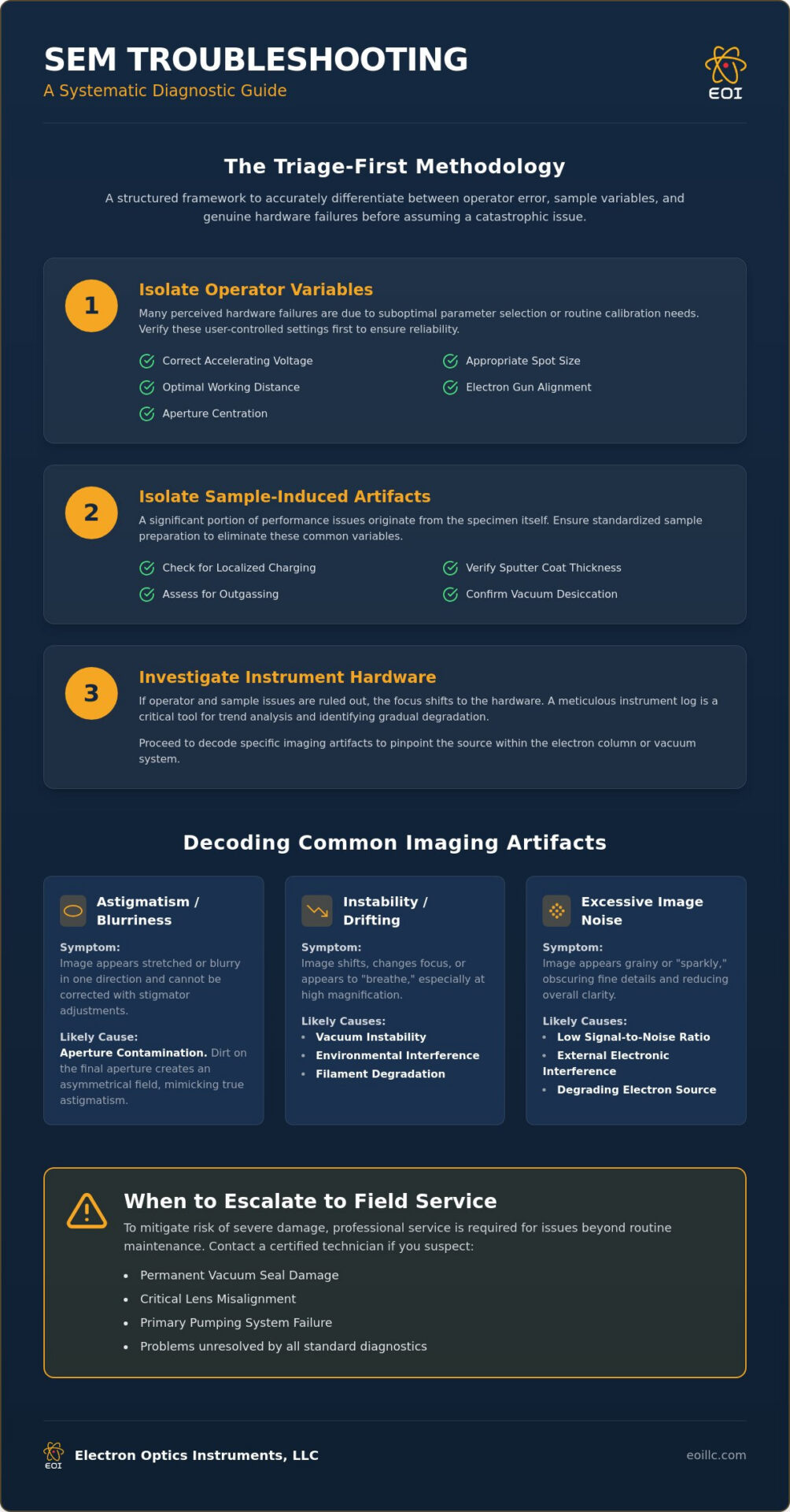
This comprehensive sem troubleshooting guide provides the systematic frameworks necessary to transition from reactive repairs to a proactive, triage-first methodology. We’ll explore a clear diagnostic matrix designed to isolate variables across the electron column and vacuum physics, ensuring your facility consistently produces high-resolution data while maximizing the longevity of your Veritas Series or Cube II systems. By aligning your internal processes with the latest ISO 25387:2026 standards, you’ll minimize downtime and reinforce the reliability of your analytical outcomes.
Key Takeaways
- Implement a systematic “Triage-First” methodology to accurately differentiate between operator error, sample preparation variables, and genuine instrument hardware failures.
- Identify the underlying physics of imaging artifacts by distinguishing between stigmator coil degradation and routine aperture contamination to restore optical clarity.
- Utilize this comprehensive sem troubleshooting guide to execute a structured diagnostic matrix, featuring baseline verification through standard sample testing and vacuum recovery analysis.
- Analyze the specific mechanics of vacuum integrity to determine whether performance instability originates within the specimen chamber or the primary pumping system.
- Recognize the critical technical thresholds for professional field service escalation to mitigate the risk of lens misalignment or permanent vacuum seal damage.
A Diagnostic Framework for SEM Performance Issues: The Triage Phase
Effective diagnostics in high-resolution microscopy require a structured departure from guesswork. This sem troubleshooting guide advocates for the ‘Rule of Three,’ a rigorous triage methodology that necessitates the isolation of the sample, the operator, and the instrument itself. Before assuming a catastrophic hardware failure, a technician must confirm that the observed artifact is not a byproduct of sample preparation or improper parameter selection. Understanding the foundational physics of a Scanning Electron Microscope (SEM) is essential during this stage, as it allows the user to differentiate between expected electron-matter interactions and anomalous system behavior. It’s often the case that localized charging or environmental interference mimics the symptoms of a degrading electron source.
Distinguishing between transient environmental noise, such as electromagnetic interference or floor vibrations, and permanent hardware degradation requires historical context. Maintaining a meticulous instrument log is not merely an administrative task; it is a critical diagnostic tool that enables trend analysis over months or years. By establishing baseline performance metrics for your specific desktop sem, such as standard signal-to-noise ratios at defined magnifications, you can identify the subtle onset of vacuum leaks or filament thinning before they result in total system failure. This methodical tracking ensures that any deviation from the established norm is detected with surgical precision.
Isolating Sample-Induced Artifacts
A significant portion of reported performance issues originates within the specimen chamber rather than the electron column. Charging occurs when non-conductive samples accumulate excess electrons, creating a localized negative field that deflects the primary beam. This often appears as sudden image shifts or “bright spots” that users mistake for beam instability. Similarly, outgassing from porous or oily samples can trigger vacuum instability and persistent image hazing. Standardizing sample preparation protocols, including consistent sputter coating thickness and vacuum desiccation, eliminates these variables. When you remove sample inconsistencies, this sem troubleshooting guide becomes a far more effective tool for identifying true mechanical discrepancies.
Operator Error vs. System Calibration
Precision imaging requires a synergy between hardware capability and operator expertise. Many perceived resolution issues are actually the result of suboptimal parameter selection, such as an inappropriate accelerating voltage or a spot size that exceeds the requirements for high-magnification work. An incorrect working distance can also compromise the depth of field and resolution, leading to a “drifting” appearance in the final data. Before diagnosing a mechanical failure, the operator should verify the alignment of the electron gun and the centration of the apertures. These routine calibrations often resolve common artifacts, ensuring that internal processes remain rigorous and instrument downtime is kept to an absolute minimum.
Decoding Imaging Artifacts: Physics of the Electron Column
When the triage phase confirms that the instrument hardware is the source of imaging degradation, the focus must shift to the internal physics of the electron column. Astigmatism remains one of the most frequent challenges in high-resolution microscopy. While operators often attempt to correct blurriness through stigmator adjustments, it’s vital to distinguish between a genuine stigmator coil failure and simple aperture contamination. Contamination on the final aperture creates an asymmetrical electrostatic field that mimics astigmatism, yet it cannot be fully compensated for by the electronics. If the beam shape remains stubbornly elliptical despite maximum correction, this sem troubleshooting guide recommends inspecting the physical integrity of the apertures before assuming a failure in the electromagnetic lenses.
Image noise presents another diagnostic hurdle, requiring a clear distinction between a low signal-to-noise ratio (SNR) and external electronic interference. A low SNR is typically a byproduct of insufficient beam current or excessively fast scan speeds. In contrast, electronic interference often manifests as periodic “banding” or “herringbone” patterns across the micrograph. Similarly, image shift and drift are frequently misidentified. While drift is often the result of thermal instability in the laboratory environment, persistent image shifts may indicate mechanical wear in the stage motors or a loss of tension in the drive assembly. High-performance systems, such as the Veritas FE SEM, utilize advanced Schottky field emission sources to mitigate these instabilities, providing a level of beam brightness and long-term consistency that far exceeds traditional tungsten systems.
Contamination and Beam Charging
Carbonaceous buildup on the final aperture or the internal column liners is a primary driver of unpredictable beam deflection. This contamination often presents as a dark “box” or shadow that appears after prolonged scanning of a single area. As the electron beam interacts with residual hydrocarbons, it deposits a non-conductive layer that eventually charges and repels the beam. While some facilities attempt in-house cleaning of sensitive components, such actions carry a significant risk of damaging the delicate electron optics or misaligning the optical axis. When internal recalibration fails to resolve persistent aberrations, seeking expert field service remains the most reliable path to restoring instrument integrity.
Environmental and Electromagnetic Interference
The precision of modern microscopy is highly sensitive to the external environment. A 60Hz “hum” or jagged edges on vertical structures in an image often point toward improper grounding or the proximity of heavy power lines. Furthermore, floor vibrations can severely limit resolution in high-magnification modes, appearing as a rhythmic blurring that corresponds to building HVAC systems or nearby foot traffic. During a professional sem operation audit, technicians verify EMI shielding by utilizing an oscilloscope to monitor signal variance against known ambient frequencies. Addressing these environmental factors is a critical step in any comprehensive sem troubleshooting guide, ensuring the laboratory environment supports the instrument’s maximum theoretical resolution.
Critical Subsystem Failure: Vacuum Integrity and Electron Sources
The operational efficacy of any scanning electron microscope is inextricably linked to the integrity of its vacuum environment. When vacuum levels degrade, the mean free path of the primary electron beam is significantly reduced, leading to increased electron scattering as the beam interacts with residual gas molecules. This phenomenon manifests as a loss of image contrast and resolution, essentially undermining the instrument’s analytical precision. Within this sem troubleshooting guide, we emphasize that identifying the root cause of vacuum instability requires a methodical assessment of both the specimen chamber and the primary pumping assembly. Differentiating between a localized leak at a specimen door seal and a systemic malfunction within the turbomolecular pump is a prerequisite for effective resolution. Consistent adherence to a professional sem maintenance schedule remains the most effective strategy for preserving these high-vacuum environments and preventing the gradual degradation of internal seals.
Electron source health is a secondary but equally vital indicator of system stability. While tungsten filaments are expected to fail after 40 to 100 hours of operation, sudden or frequent burnouts often signal underlying vacuum leaks or high-voltage power supply fluctuations. A premature failure is rarely an isolated event; it’s typically a symptom of oxygen ingress into the column or an unstable emission current. In high-performance systems like the Veritas Series, monitoring the emission stability and the extractor voltage provides a visionary outlook on source longevity, allowing laboratories to plan for replacements before a catastrophic failure halts production.
Vacuum System Diagnostics
Isolating a vacuum failure begins with a rigorous analysis of pump-down times. A roughing pump failure typically presents as an inability to reach the crossover pressure required for the high-vacuum pumps to engage. Conversely, if the system reaches initial vacuum but fails to maintain the high-vacuum threshold, the turbomolecular pump may be experiencing bearing wear or electronic controller issues. O-ring failure is frequently identified through a “step-wise” analysis of vacuum recovery times after sample exchange. It’s also critical to note that vacuum instability directly compromises the accuracy of EDS (Energy Dispersive Spectroscopy) systems, as gas molecules interfere with X-ray detection and increase background noise levels.
Electron Source Longevity
The diagnostic path for electron sources varies significantly between traditional tungsten filaments and Field Emission (FE) sources. While tungsten filaments require manual centering and saturation, FE sources rely on ultra-high vacuum levels to maintain a stable emission tip. Emission instability in an FE source can often be resolved by “flashing” the tip, a process that removes adsorbed gas molecules through a brief thermal pulse. However, if emission remains erratic after flashing, it may indicate a failing high-voltage power supply or a breach in the column’s ultra-high vacuum integrity. Technical indicators such as erratic beam current readings or persistent flickering in the live view are the primary signals that the electron source or its associated power electronics require professional intervention.
Systematic Troubleshooting Matrix: A Step-by-Step Diagnostic Path
A rigorous sem troubleshooting guide requires a methodical progression from simple verification to complex subsystem analysis. The first step in any diagnostic protocol is the ‘Standard Sample’ test. By utilizing a known reference, such as gold-on-carbon or a Faraday cup, technicians can verify the instrument’s baseline performance without the interference of unknown sample variables. If the standard sample produces a crisp, high-contrast image, the issue is likely rooted in the specific specimen or its preparation rather than the hardware itself. This foundational check prevents the unnecessary disassembly of sensitive components.
Following baseline verification, it’s essential to check vacuum recovery times against the manufacturer’s original specifications. Deviations often indicate the early stages of O-ring degradation or pump efficiency loss. Technicians should then evaluate beam alignment and aperture cleanliness, as even minor misalignments in the electron gun can simulate more severe electronic failures. Once these physical parameters are confirmed, the operator can analyze specific image artifacts using the EOI diagnostic matrix. Documenting these findings meticulously ensures that if the issue persists, the subsequent professional service response is both rapid and targeted, saving valuable laboratory resources.
The SEM Diagnostic Matrix
This matrix serves as a primary tool for distinguishing between user-fixable maintenance and issues requiring expert intervention. It’s designed to provide a visionary framework for maintaining instrument uptime through technical meticulousness.
| Symptom | Likely Cause | Recommended Action |
|---|---|---|
| Image Stretching | Stage motor wear or sample charging | Verify sample grounding; if persistent, call service. |
| Periodic Noise (Banding) | Ground loop or electromagnetic interference | Check cable shielding and laboratory power stability. |
| Slow Pump-Down | Contaminated O-ring or failing roughing pump | Clean specimen chamber seals; check pump oil levels. |
Data Integrity and Software Errors
Modern microscopy is as much a digital endeavor as it is a physical one. Communication errors between the SEM hardware and the control PC often stem from faulty interface cables or driver conflicts within the operating system. If you’re experiencing software-induced image lag or reconstruction artifacts, it’s vital to check system resource allocation and ensure that background processes aren’t throttling the acquisition software. Firmware updates often play a decisive role in resolving persistent system glitches that mimic hardware failures. For complex integration issues that exceed standard software troubleshooting, we recommend engaging professional SEM field support to ensure data integrity is maintained through rigorous technical calibration.
Professional Resolution: When to Escalate to Field Service
While the protocols established in this sem troubleshooting guide empower laboratory personnel to resolve routine operational discrepancies, certain technical thresholds require the intervention of a certified field service engineer. Unauthorized disassembly of the electron column or the vacuum manifold introduces a high probability of irreversible lens misalignment or catastrophic vacuum seal failure. These precision components are engineered to tolerances that exceed standard laboratory capabilities; attempting complex internal repairs without specialized alignment jigs often results in a permanent loss of resolution. By recognizing the transition point between user-level triage and professional service, facility managers can protect their initial capital investment and ensure the long-term viability of their analytical infrastructure.
Managing the total electron microscope cost necessitates a strategic approach to maintenance that prioritizes comprehensive service contracts over reactive, out-of-pocket repairs. The return on investment for expert troubleshooting is realized through the prevention of system-wide failures in high-performance hardware like advanced microscopy systems. Electron Optics Instruments, LLC leverages over 30 years of industry experience to provide authoritative support across a diverse range of advanced microscopy platforms. This depth of expertise ensures that diagnostic protocols are executed with a meticulousness that mirrors original manufacturing standards, effectively neutralizing the risk of cumulative hardware degradation.
The Electron Optics Instruments, LLC Field Service Advantage
Electron Optics Instruments, LLC provides national support for complex hardware failures, offering a level of technical integration that is difficult to replicate in-house. Our field service engineers have access to specialized replacement parts and high-precision calibration tools that are essential for restoring the optical axis of precision microscopy instruments. Beyond traditional repairs, our team provides on-site technical training to refine internal diagnostic capabilities. We also offer professional relocation services, ensuring that instrument performance is meticulously verified after laboratory moves, maintaining the synergy between industrial performance and logistical excellence.
Future-Proofing Your Lab
Transitioning from reactive troubleshooting to a proactive modernization strategy is essential for laboratories focused on sustainable development and high-end quality. Electron Optics Instruments, LLC supports the entire lifecycle of industrial and research microscopy, from initial deployment to ongoing maintenance of your critical SEM equipment. By integrating regular preventative maintenance visits, you ensure that your hardware remains at the cutting edge of technological possibility. If your current diagnostic matrix indicates a failure beyond the scope of this sem troubleshooting guide, it’s time to leverage professional expertise. Contact Electron Optics Instruments, LLC for professional SEM troubleshooting and repair to restore your facility’s high-resolution capabilities.
Advancing Analytical Excellence through Technical Meticulousness
Mastery of the electron column requires more than just operational knowledge; it demands a structured departure from reactive maintenance. By implementing the triage-first methodology and the systematic diagnostic matrices outlined in this sem troubleshooting guide, your facility can effectively distinguish between transient environmental noise and critical hardware degradation. This proactive approach ensures that instrument downtime is minimized and the integrity of your high-resolution data remains uncompromised across every imaging session, reinforcing the reliability of your analytical outcomes.
When internal protocols reach their technical limits, engaging with a seasoned global innovator is the next logical step for your laboratory’s growth. Electron Optics Instruments, LLC brings over 30 years of specialized expertise to every engagement, offering national service for all major SEM brands, including JEOL, Hitachi, and Zeiss. As the sole US distributor for EmCraft, we’re uniquely positioned to support the entire lifecycle of your microscopy hardware through superior standards of accuracy. Request a Professional SEM Diagnostic Consultation from Electron Optics Instruments, LLC to reinforce the reliability of your research and industrial production. We look forward to helping you maintain the highest standards of precision in your laboratory operations.
Frequently Asked Questions
Why is my SEM image suddenly blurry at high magnification?
Sudden blurriness at high magnification is frequently the result of uncorrected astigmatism or carbonaceous contamination on the final aperture. When the electron beam interacts with buildup on the aperture, it creates an asymmetrical electrostatic field that prevents the beam from focusing into a perfect circle. This sem troubleshooting guide recommends verifying the stigmator settings and inspecting the physical integrity of the apertures before you assume a more complex electronic failure.
How can I tell if my SEM vacuum system has a leak?
Vacuum integrity issues are typically identified by a measurable increase in pump-down times or the inability of the system to reach its established crossover pressure. If the turbomolecular pump fails to reach its rated RPM or if the specimen chamber pressure fluctuates during stage movement, a localized leak at the O-ring or door seal is likely. Consistent monitoring against manufacturer specifications is essential for identifying these subtle performance deviations before they compromise the electron source.
What causes periodic noise or horizontal lines in my SEM images?
Periodic noise manifesting as horizontal lines or “herringbone” patterns is usually caused by electromagnetic interference or ground loops within the laboratory environment. This artifact often correlates with the 60Hz frequency of local power grids or the proximity of high-voltage industrial equipment. Verifying the integrity of the instrument’s grounding cable and ensuring that all signal cables are properly shielded can mitigate these disruptive electronic signatures and restore image clarity.
How often should I change the oil in my SEM vacuum pumps?
Standard maintenance protocols require changing the oil in rotary vane roughing pumps every six months, although high-throughput environments often necessitate more frequent intervals. You should monitor the oil clarity through the sight glass; a transition from transparent to a dark or milky appearance indicates saturation with contaminants or moisture. Neglecting this schedule risks pump efficiency loss and the potential for oil backstreaming into the sensitive specimen chamber.
Is it safe to clean the SEM column apertures myself?
Cleaning the internal column apertures is a high-precision task that is generally discouraged for operators due to the extreme risk of damaging the delicate electron optics. Even minor scratches or the introduction of microscopic lint can cause severe beam aberrations that require expensive professional recalibration. This sem troubleshooting guide advises that aperture cleaning or replacement should be handled during a professional preventative maintenance visit to ensure continued optical alignment and system integrity.
What are the signs that my SEM filament is about to fail?
A tungsten filament nearing the end of its operational life typically displays erratic emission current and a requirement for higher saturation voltages to maintain beam stability. You may also observe “flickering” in the live image or a sudden decrease in the signal-to-noise ratio during routine operations. Meticulous tracking of filament hours in the instrument log allows for scheduled replacements before a total burnout occurs and halts your critical imaging sessions.
Why does my sample appear to be moving or ‘drifting’ during imaging?
Image drift is commonly attributed to thermal instability as the sample and stage reach equilibrium after being introduced into the vacuum chamber. In some instances, mechanical wear in the stage drive assembly or the use of non-rigid mounting media can also cause perceived movement at high magnifications. Ensuring that samples are properly desiccated and allowed to stabilize for several minutes before imaging will significantly reduce these frustrating artifacts and improve data accuracy.
How do I distinguish between electrical noise and vibration artifacts?
Distinguishing between these two artifacts requires an analysis of the interference pattern; electrical noise is typically periodic and synchronized with scan rates, while vibration artifacts appear as jagged edges or “sawtooth” patterns. Vibration is often non-periodic and can be traced to building HVAC systems or nearby foot traffic. Utilizing an oscilloscope to monitor the signal output during scan acquisition provides the technical clarity needed to isolate the specific environmental source.